


TOOLS YOU WILL FIND HANDY • Adjustable Wrench • Pliers
WHERE TO MOUNT YOUR ANTENNA
Your antenna can be mounted on either the chimney, the roof, or on an outside wall or in an attic. Choose the
method that best suits your particular location. Mast tube size should be 1.25” to 1.66” outside diameter.
TRANSMISSION LINE
75 Ohm coaxial cable. RG-6 if running long distance. RG-6 or RG-59 for short distance.
ASSEMBLING ANTENNA
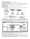
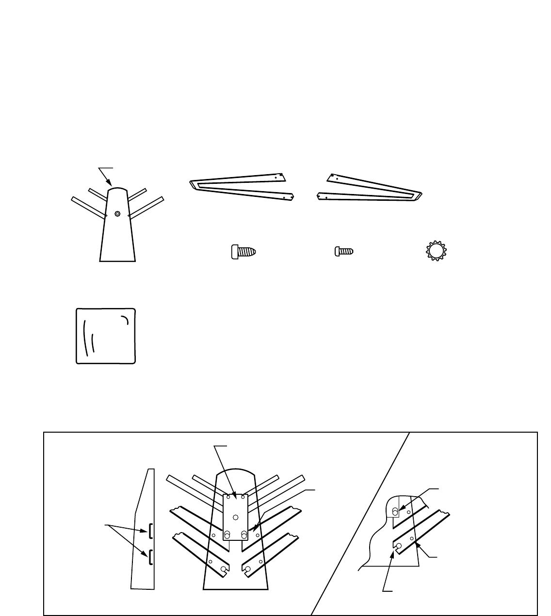
STEP 1: Remove the bottom cover from the unit. Unsnap the cover from the front end and clam shell open.
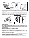
STEP 2: With the internal (cavity) part of the housing facing you, slide the left VHF element through the slots in
the left side of the housing. See FIGURE A. Be sure the element slides under the PCB. Slide the element all the
way in so that the slots in the elements are totally around the pre-installed screws. Note: The four screws are
only turned down half way. See FIGURE B.
Front End
Hardware Bag
2 - M4 x 10mm self tap screws (cover) 2 - M6 x 70mm hex head bolts
4 - M6 x 12mm self tap screws (VHF elements) 2 - M6 flat washers
1 - mounting nest (mast) 1 - rubber weather boot
4 - M6 external tooth lockwashers
LEFT
SIDE
RIGHT
SIDE
Main Unit
(bottom view)
VHF element
LEFT side
VHF element
RIGHT side
4 - M6 x 12mm
self tap screws
2 - M4 x 10mm
self tap screws
4 - M6 external
tooth lockwashers
PCB
VHF element
to slide
under PCB
Pre-installed
screw (halfway
turned down "4")
Line up the holes
in the element with
the holes in the
mounting bosses
Slide element slot in all of
the way (2 slots per element)
VHF slots
in housing
LEFT SIDE INSIDE VIEW
+
+
++
+
+
+
+
FIGURE A FIGURE B
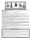
STEP 3: After the elements are totally in place, tighten the two pre-installed screws. Tighten to the point where
the element and PCB feel tight. Do not over tighten. This may result in stripping threads.
STEP 4: Repeat steps 2 and 3 for the opposite side.
STEP 5: Remove the four M6 x 12mm screws and four M6 external tooth lockwashers from the hardware bag.
Install them into the four remaining mounting holes. See FIGURE C.
STEP 6: Reinstall the cover. Be sure the two tabs on the back end of the cover slips into the two slots in the rear
wall of housing. See FIGURE D. Clam shell the cover shut and snap the front end in place. Install the two
M4 x 10mm cover screws. See FIGURE D. Do not over tighten.