


OUTPUTS
CLASS 2 WIRING
1
1234
2 3
(BRIDGE A) (BRIDGE B)
4
ON
OFF
AB
12 34
LEVEL
REMOTE
LIMITER/
PROTECT
SIGNAL
STANDBY
INPUTS
XPA 2004
BRIDGE
MODE
BRIDGE 8 ONLY
(
)
4/8
BRIDGE 8 ONLY
(
)
4/8
1234
BRIDGE A BRIDGE B
GREEN - ACTIVE
AMBER - STANDBY
100-240V 1.5A, 50-60 Hz
LISTED
AUDIO/VIDEO
APPARATUS
17TT
N15779
0
2
4
6
8
10
14
18
26
12
0
2
4
6
8
10
14
12
0
2
4
6
8
10
14
12
0
2
4
6
8
10
14
12
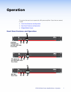
5
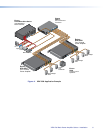
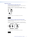
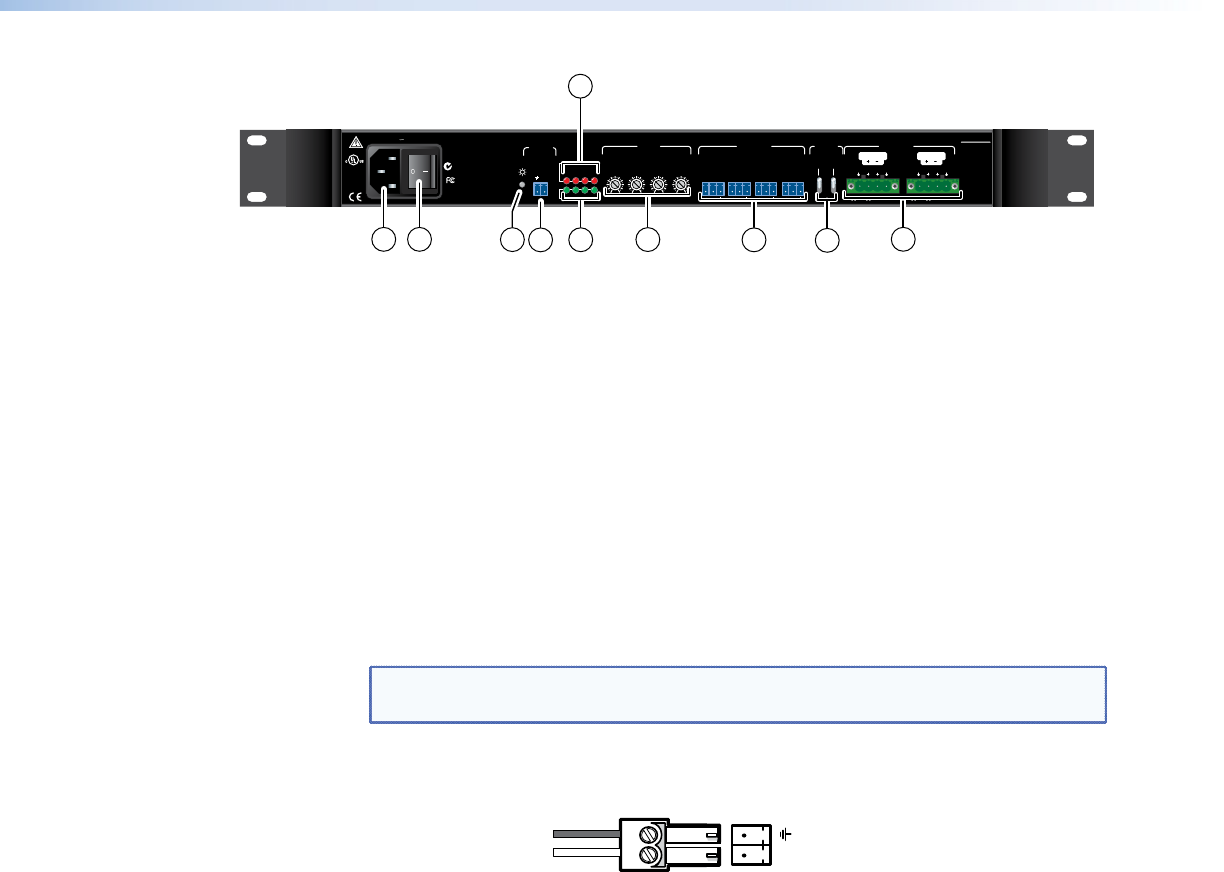
XPA 2004
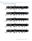
Rear Panel
1 2
4
6
7
8
11
12
3
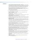
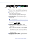
a AC power connector — Connect a standard IEC AC power cord here for power
input (100 VAC to 240 VAC, 50/60 Hz) to the internal, autoswitching power supply.
b Power switch — This rocker switch turns power to the amplifier on or off. The off
position also disables remote standby (see d).
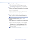
c Power indicator LED — This LED lights:
• Greenwhentheamplierisreceivingfullpower.
• Amberwhentheamplierisinstandbymode.Standbymodeturnsoffall
outputs from the amplifier, although the amplifier is still receiving power.
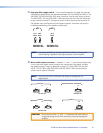
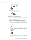
d Remote standby connector — Connecting pin 2 to ground (pin 1) places the
amplifier in standby mode. Standby mode turns off all outputs, although the amplifier
is still receiving power.
NOTE: The amplifier automatically enters standby mode after 25 minutes of
inactivity (+/- 5 minutes).
Use the included 2-pin, 3.5 mm captive screw connector to jumper the pins.
To Contact Closure Port
on Control Device
STANDBY
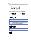
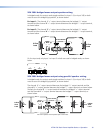
e Limiter/Protect indicator LEDs (channels 1, 2, 3, and 4) — These LEDs
(representing output channels 1, 2, 3, and 4) light red under four circumstances:
• Whenaudioclippingoccurs,theLEDofthecorrespondingchannelblinksonce
per clip occurrence.
• Whentheamplieroverheats,bothLEDsarelit.TheLEDsarenotlitafterthe
amplifier cools down and recovers from the overheated condition.
• WhenDCoutputisdetected,theamplierismalfunctioningandtheLED for
the corresponding channel is lit.Whenamalfunctionoccurs,powerdownthe
amplifier and power it back up. If the LED still remains lit, the amplifier requires
servicing.
• Whentheoutputleadsareshorted,theLEDofthecorrespondingchannelislit
until the short is removed.
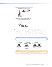
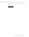
f Signal indicator LEDs (channels 1, 2, 3 and 4) — These LEDs (representing input
channels 1, 2, 3 and 4) light green only when an input signal is detected on the
corresponding channel.
XTRA Full Rack Power Amplier Series • Operation 10