


NetworX NX-548E Receiver
Installation Instructions
2
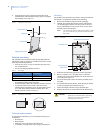
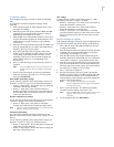
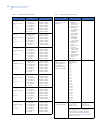
6. Align the bottom of the circuit board in the edge guide
standoff and twist the standoff into place (Figure 4). Tighten
the mounting screw (Figure 2).
Figure 4. Installing the circuit board
External mounting
This installation uses enclosure model NX-569 (600-1029-03).
The module comes as a kit that is assembled in the field. Use the
following installation guidelines:
• Allow at least 10 in. (25 cm) of clearance above the enclo-
sure for the antennas.
• Use the wire length guidelines in Table 1.
• Install the module in its own plastic enclosure. It should not
be installed inside the panel’s enclosure.
• Avoid mounting locations that expose the module to moisture.
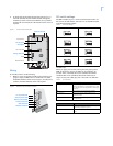
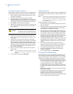
• Avoid areas with excessive metal or electrical wiring
including furnace and utility rooms. If unavoidable, mount
on or near metal with the antenna extending above the
metallic surfaces as shown in Figure 5.
Figure 5. Mounting on or near metal
Tools and supplies needed
To complete the installation, you will need the following tools
and supplies:
• Screwdrivers;
• Drill with bits;
• Mounting screws and anchors (included); and
• 3-conductor, 22-gauge (0.65 mm) or larger, stranded wire.
Mounting
The module can be mounted on any interior wall (protected from
the elements). To mount the module, do the following:
1. Remove the module back plate from the packaging.
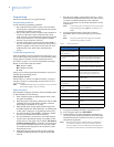
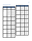
2. Hold the base against the mounting surface and mark the
two mounting holes and the wire access hole as shown in
Figure 6. Remember to leave at least 10 in. (25 cm) above
the back plate for the antennas.
Note: The wire access hole is molded into the plastic so that
you can access the wire, yet keep it hidden from the
back plate.
Figure 6. Back plate
3. Drill holes and insert the appropriate anchors (included).
4. Run a 3-conductor, 22 or 18 gauge (0.65 or 1.02 mm)
stranded wire cable from the module wire access hole loca-
tion to the panel (Figure 6).
5. Secure the back plate to the wall with the pan head screws
provided.
6. To assemble the antenna shrouds, attach the proper number
of sections together, then attach the top cap.
7. Install each antenna shroud on top of the back plate.
8.
Remove the transceiver circuit board from the antistatic
bag.
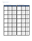
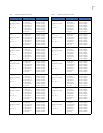
Table 1. Wire lengths
Wire gauge (shielded or unshielded)
Maximum wire length between
module and panel
22 AWG (0.65 mm) 250 feet (76 m)
18 AWG (1.02 mm) 500 feet (152 m)
Circuit board
Edge guide standoff
Antenna shroud
Enclosure
Metal Metal
CAUTION
You must be free of static electricity before
handling circuit boards. Wear a grounding
strap or touch a bare metal surface to
discharge static electricity.
Antenna shroud locations
Mounting hole
Mounting hole
Wire access