


– 10 –
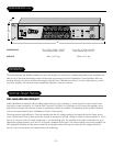
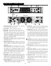
1. Recessed Front Panel - Prevents switches and controls from
accidentally being adjusted or broken.
2. Power Switch - Turns the amplifier ON and OFF
3. Power LEDs - Verifies that the amplifier channel is ON
4. Status LEDs - Displays the status of the amplifier. The LEDs
are as follows: SIGNAL indicates if signal is present; CLIP
illuminates if the amplifier is being overdriven; PROTECT
illuminates if the amplifier is experiencing a “short” in the
speaker array; THERMAL illuminates if the amplifier has shut
down due an overheating condition.
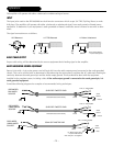
5. Female XLR & 1/4" TRS Input Jacks - Feeds input signal to
the amplifier using industry standard male XLR or 1/4" TRS
(tip/ring/sleeve) plugs.
6. Male XLR Daisy Chain Jacks - Enables the connection of
multiple amplifiers. The signal derived from the input
signal is directly passed through (daisy chained) to these
output jacks.
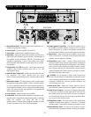
7. Stereo/Mono Switch - This dual purpose switch is used to
select the operating mode of the amplifier. In Stereo mode
the amplifier can be configured for standard 2-channel
stereo operation. In Mono mode the amplifier can be con-
figured for Standard Bridge mono, 70V mono or 100V mono
operation. Turn amplifier off before operating this switch.
8. Level Controls - Adjusts the gain of the amplifier.
9. Load Switch - Selects the speaker impedance or transformer
voltage that will be connected the output binding posts. In
Standard Mode the amplifier can drive 2Ω, 4Ω or 8Ω
speaker loads. In Constant Voltage Mode the amplifier can
drive an array of speakers using 70V or 100V transformers.
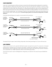
10. Output Binding Posts - Connects the speaker array to the
amplifier. These jacks allow bare wire, spade lugs or dual
banana plugs to be connected to the amplifier.
11. Internal Fans - internal fans keep the amplifier circuitry
cool. Allow a minimum of 3" clearance on the front and
back of the amplifier vents for adequate ventilation.
12. Chassis/Float ground switch - Isolates Audio Ground from
Chassis Ground (Chassis Ground is permanently connect-
ed to Earth Ground through the third pin of the power
cord). With the switch in the "Chassis" position, the Audio
Ground is connected to Chassis Ground. In the "Float" posi-
tion, Audio Ground is isolated ("floated") from Chassis
Ground, and must be connected to Earth Ground by other
means.
CAUTION: Do not attempt to "float" Audio Ground from
Chassis Ground unless you are absolutely certain there is
some other common ground between the amplifier and the
source equipment. Without this common ground, oscilla-
tions and severe damage may occur.
13. Mains Power Fuse - Protects the “mains” electrical circuit
in case abnormal current draw from the amplifier is expe-
rienced.
14. Mains Power Connector - Connects AC Voltage to the
amplifier. The power connector is safety approved IEC type
320. The earth (safety) ground pin of the power connector
is permanently connected to the chassis. This connection is
capable of shunting in excess of 30A of fault current.
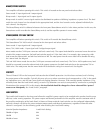
15. Biamp/Stereo Switch - This dual purpose switch selects
either standard 2-channel stereo mode or 1-channel in, 2
channels out Biamp mode. Turn amplifier off before oper-
ating this switch.
16. Removable Rear Panel - 8 screws can be removed to ser-
vice fans and internal components without unracking the
amplifier.
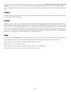
FRONT VIEW
REAR VIEW
BIAMP STEREO
CH A
IN
–
+
CH B
IN
CH A
OUT
CH B
OUT
+
–
–
+
(Mono)
Chassis
Float
Audio GND
3
21
+
–
+
–
Attention: Utiliser un fusible
de rechange de même type.
CAUTION: For continued
protection from risk of fire,
replace only with same type
and rating of fuse.
A Division of
Rockford Corp.
Tempe, AZ 85281
Made in the U.S.A.
SR2800
700 W Stereo, 2Ω– 8Ω
1400W Mono,
®
460W
100V-120V~
50/60Hz
250V T15A
Class 2 wiring
Mono,70V,100V
1200W
For 70V, 100V, or Mono
• Use CH B input
• Load across RED
terminals
• Set load switches to one
4Ω– 16Ω
600W
2Ω – 8Ω
600W
2Ω – 8Ω
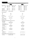
Design Features – SR2300, SR2800
!