


R7824, R7847, R7848, R7849, R7851, R7852, R7861, R7886 AMPLIFIERS FOR 7800 SERIES AND R7140 RELAY MODULES
Automation and Control Solutions
Honeywell International Inc.
1985 Douglas Drive North
Golden Valley, MN 55422
customer.honeywell.com
® U.S. Registered Trademark
© 2011 Honeywell International Inc.
65-0109—14 M.S. Rev. 06-11
Printed in U.S.A.
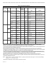
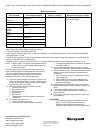
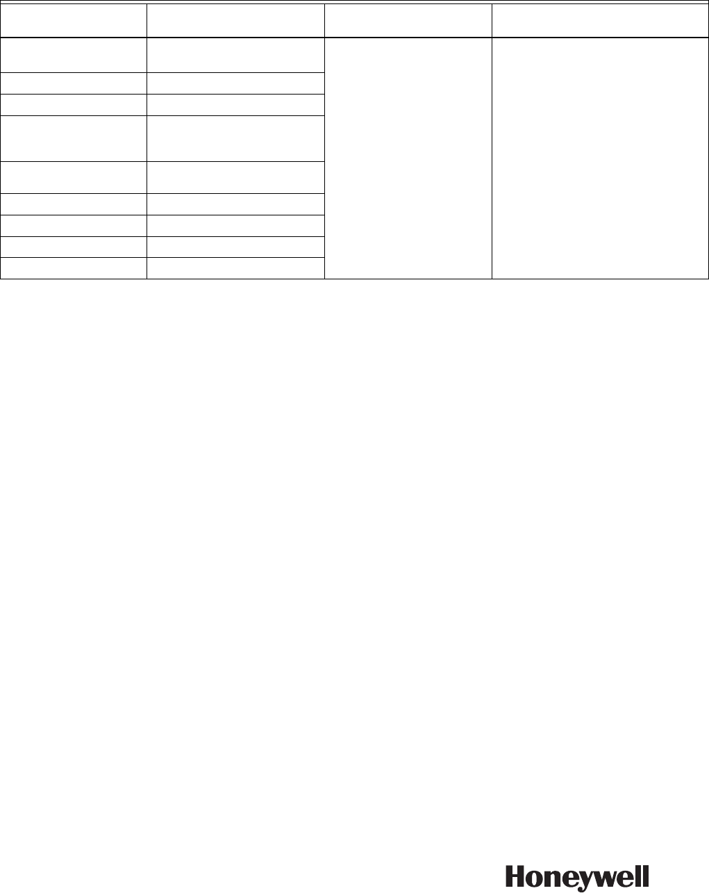
Table 3. Flame signal.
a
This minimum or stronger signal can be easily obtained if the detector is correctly installed and positioned to properly sense the
flame. Obtain this voltage before completing checkout.
b
The flame amplifiers are Ampli-Check® type.
c
Adjust slightly, or face the pipe down, or extend the sight pipe on C7012A,C applications to obtain a maximum flame signal
reading less than 5.0 volts.
d
The flame signal amplifier circuitry is tested one-half second every five seconds during burner operation and shuts down the
burner if the amplifier fails (all installations).
e
R7824C Series 2 or greater and R7847C Series 4 or greater, pulse the shutter when the flame signal reaches 1.5 Vdc.
NOTE: R7824C, Series 2 or greater, pulse shutter when sig-
nal of 1.5 Vdc is sensed. Display readings of 0.7 to
2.4 Vdc are common.
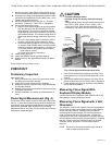
The flame signal for the pilot alone, the main burner flame
alone, and both together must be steady and a minimum of
1.25V. If the flame signal is unsteady, or less than the
minimum acceptable voltage, check the flame detector
installation and circuitry in the following procedure.
1. Check the supply voltages at terminals (L1) and L2 (N).
Make sure the master switch is closed, connections are
correct, and the power supply is of the correct voltage
and frequency and is sinusoidal.
2. Check the detector wiring for defects including:
a. Incorrect connections.
b. Wrong type of wire.
c. Deteriorated wire.
d. Open circuits.
e. Short circuits.
f. Leakage paths caused by moisture, soot or accu-
mulated dirt.
3. For a flame rod, make sure:
a. There is enough ground area.
b. The flame rod is properly located in the flame.
c. Temperature at the flame rod insulator is no greater
than 500°F (260°C).
4. For all optical detectors, clean the detector viewing
window, lens, and inside of the sight pipe as applicable.
5. With the burner running, check the temperature at the
detector. If it exceeds the detector maximum rated
temperature:
a. Add a heat block to stop conducted heat traveling
up the sight pipe.
b. Add a shield or screen to reflect radiated heat.
c. Add cooling (refer to sight pipe ventilation in the
detector Instructions).
6. Make sure that the flame adjustment is not too lean.
7. Make sure the optical detector is properly sighting the
flame.
8. If necessary, resight or reposition the detector.
9. If you cannot obtain proper operation, replace the
plug-in amplifier.
10. If you cannot yet obtain proper operation, replace the
flame detector.
IMPORTANT
If you make any changes to the flame detection
system, repeat all required Checkout tests in
Checkout section of the Instructions for the
applicable 7800 SERIES and R7140 Relay Module.
Flame Detector Flame Signal Amplifier
Minimum Acceptable
Steady dc Voltage
a
Maximum Expected dc Voltage
Flame Rod
C7012A,C
c
R7847A,B
b
1.25 Vdc 5.0 Vdc at Keyboard Display Module
or on volt-ohmmeter.
C7015A
R7848A,B
b
C7024E,F
R7824C
d,e
C7027A
C7035A
C7044A
R7849A,B
b
C7927
C7962
R7851B
b
C7915
R7852A,B
b
C7061A
R7861A
d
C7076A,D
R7886A
d
C7961E
R7851C
d