5
GND
AC INLET
L
R
IN
12
V
TRIGGER
OFF
AUDIO
MIN
MAX
OUT
IN
L
L
R
R
SPEAKERS
L
R
AUDIO
12 V
TRIGGER
INPUT
LEVEL
TRIGGER
CAUTION:
SPEAKER IMPEDANCE
6 OHMS MIN. PER EACH
SPEAKER TERMINAL
R
R
R
L
L
L
PB
PR
Y
P
B
PR
Y
P
B
PR
Y
COMPONENT
VIDEO
REMOTE
CONTROL
PRE
OUT
R
L
(
SB
)
ANTENNA
VIDEO
1
V
IDEO
2
DVD
MON
ITOR
OUT
ZONE 2
OUT
V
IDEO
3
R
L
INPUT 1
INPUT 2
OUTPUT
VIDEO
S VIDEO
GND
DIGITAL
OUTPUT
(
OPTICAL
)
DIGITAL
INPUT
(
OPTICAL
)
DIGITAL
INPUT
(
COAXAL
)
1
2
1
2
FRONT
SURR
SURR
BACK
SUB
WOOFER
MULTI CHANNEL
INPUT
FRONT
SURR
SURR
BACK
SUB
WOOFER
OUT
TAPE
CD
PH
R
L
VIDEO
S VIDEO
OUT
OUT
I
N
I
N
I
N
I
N
FRONT
SPEAKERS
SURR
SPEAKERS
SURR
BACK
SPEAKER
ZONE 2
SPEAKERS
CENTER
SPEAKER
CENTER
MAIN
ZONE 2
(
SB
)
CENTER
R
L
ZONE 2
MAIN
AC OUTLETS
AC 120V 60Hz
SWITCHED
TOTAL 120W 1A MAX.
IR IN
AM
IN
FM
75
R
L
2 CHANNEL AMPLIFIER
MODEL NO. ADM-2.1
AV RECEIVER
MODEL NO. DTR-7.1
12 V
TRIGGER
BA
RS
232
AC INLET
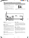
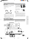
Rear panel facilities and connections
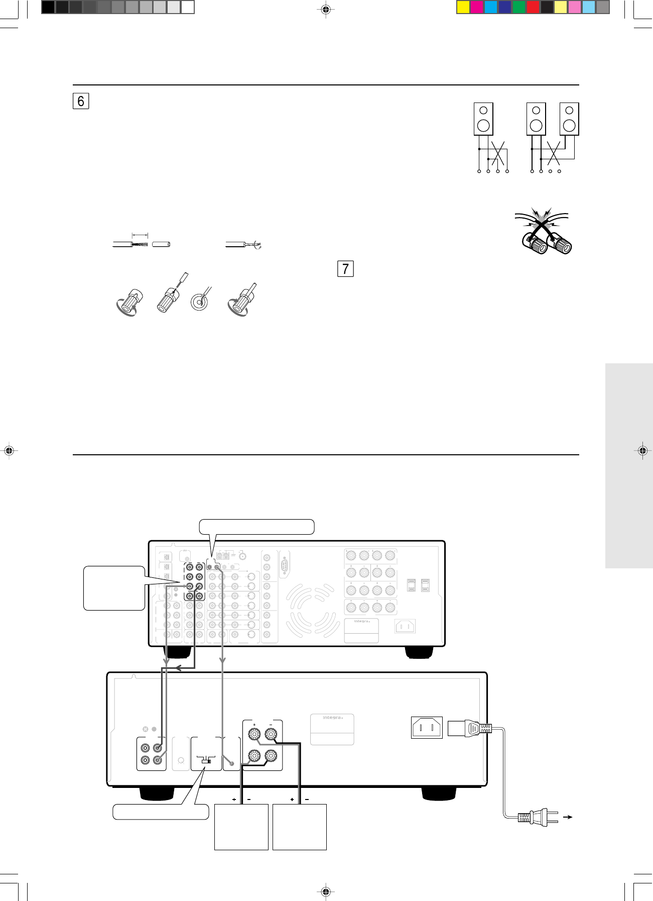
SPEAKERS
Connect the jacks on the speakers to the SPEAKERS terminals
using the speaker cables. These terminals are compatible with
banana plug connections.
1 Strip away 15 mm (
5
/
8
in.) of wire insulation.
2 Twist wire ends very tight.
3 Unscrew.
4 Insert wire.
5 Screw.
• Do not connect any devices other than speakers to these
terminals.
• Be sure not to mistake the positive and negative outputs or the
left and right speakers. Doing so will result in an unnatural
sound space.
• Only connect speakers with an impedance of 6 ohms or higher.
If a speaker with an impedance of less than 6 ohms is
connected, it may damage the ADM-2.1.
• When you are using only one
speaker or when you wish to
listen to monaural (mono)
sound, a single speaker should
never be connected in parallel
to both the right and left-
channel terminals simultane-
ously.
• To prevent damage to cir-
cuitry, never short-circuit the
positive (+) and negative (–)
speaker wire.
AC INLET
Plug the supplied power cord into this AC INLET and then into the
power outlet on the wall.
• Do not use a power cord other than the one supplied with the
ADM-2.1. The power cord supplied is designed for use with
the ADM-2.1 and should not be used with any other device.
• Never disconnect the power cord from the ADM-2.1 while the
other end is plugged into the wall outlet. Doing so may cause
an electric shock. Always connect by plugging into the wall
outlet last and disconnect by unplugging from the wall outlet
first.
Connection diagram
Set to 12V TRIGGER.
To an AC
wall outlet
Power cord
(supplied)
Surround
back right
speaker
Surround
back left
speaker
12V TRIGGER OUT jack
PRE OUT
SURR BACK
jacks
15mm
(
5
/
8
in.)
1
34 5
2
+––+ +––+
RL RL
NO!
NO!
DTR-7.1
ADM-2.1
Since the many users will purchase the ADM-2.1 together with the
DTR-7.1, here is an explanation of how to connect the ADM-2.1 to
the DTR-7.1.
When connecting the ADM-2.1 to 2 channel control amplifier or
preamplifier, connect the AUDIO IN jacks of the ADM-2.1 to the
PRE OUT FRONT jacks of the control amplifier or preamplifier,
and connect the front speakers to the SPEAKERS terminals of the
ADM-2.1.
#US_ADM-2.1_04-07.p65 8/25/00, 6:22 PM5


