


INSTALLATION
WARNING: Playing loud music
in an automobile can hinder your
ability to hear traffic and permanently
damage your hearing. We recommend
listening at low or moderate levels
while driving your car. JBL accepts
no liability for hearing loss, bodily
injury or property damage resulting
from the use or misuse of this product.
IMPORTANT: To get the best
performance from your JBL Power
Series
®
amplifiers, we strongly recom-
mend that installation be entrusted to
a qualified professional. Although
these instructions explain how to
install JBL Power Series amplifiers in
a general sense, they do not show
specific installation methods that may
be required for your particular vehicle.
If you do not have the necessary tools
or experience, do not attempt the
installation yourself. Instead, please
ask your authorized JBL car audio
dealer about professional installation.
INSTALLATION
WARNINGS AND TIPS
• Always wear protective eyewear
when using tools.
• Turn off all audio systems and other
electrical devices before you start.
Disconnect the (–) negative lead from
your vehicle’s battery.
• Check clearances on both sides of a
planned mounting surface before
drilling any holes or installing any
screws. Remember that the screws
can extend behind the surface.
• At the installation sites, locate and
make a note of all fuel lines,
hydraulic brake lines, vacuum lines,
and electrical wiring. Use extreme
caution when cutting or drilling in
and around these areas.
• Before drilling or cutting holes, use
a utility knife to remove unwanted
fabric or vinyl to keep material from
snagging in a drill bit.
• When routing cables, keep input-
signal cables away from power
cables and speaker wires.
• When making connections, make
certain they are secure and properly
insulated.
• If the amplifier’s fuse must be
replaced, use only the same type and
rating as that of the original. Do not
substitute another kind.
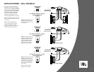
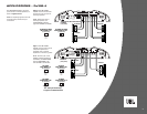
CHOOSING A LOCATION
AND MOUNTING THE
AMPLIFIER
Amplifiers need air to stay cool.
Suitable locations are under a seat
(provided the amplifier doesn’t
interfere with the seat adjustment
mechanism), in the trunk, or in any
other location which provides enough
air for the amp to cool itself. Do not
mount the amplifier with the heat sink
facing downward, as this makes
convection cooling of the amplifier
impossible.
Mount the amplifier so that it is not
damaged by the feet of backseat
passengers or shifting cargo in the
trunk. Mount the amplifier so that it
remains dry – never mount an amplifier
outside the car or in the engine
compartment. Using the amplifier as
a template, mark the location of the
mounting holes on the mounting
surface, drill pilot holes, and attach
the amplifier to the mounting surface
with screws. Make sure the amplifier
is mounted securely.
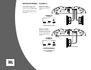
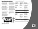
POWER CONNECTIONS
The Power Series amplifiers are
capable of delivering extremely high
power levels, and require a heavy-duty
and reliable connection to the vehicle’s
electrical system in order to perform
optimally. Please adhere to the
following instructions carefully:
Ground Connection
Connect the amplifier’s Ground (GND)
terminal to a solid point on the
vehicle’s metal chassis, as close to
the amplifier as possible. Refer to the
chart below to determine minimum
wire-gauge size. Scrape away any
paint from this location; use a star-type
lock washer to secure the connection.
Power Connection
Connect a wire (see chart at right for
appropriate gauge) directly to the
vehicle’s positive battery terminal,
and install an appropriate fuse holder
within 18" of the battery terminal.
Do
not install the fuse at this time.
Route
the wire to the amplifier’s location, and
connect it to the amplifier’s Positive
(BATT +) terminal. Be sure to use
appropriate grommets whenever
routing wires through the firewall
or other sheet metal.
Failure to
adequately protect the positive wire
from potential damage may result in
a vehicle fire.
When you are done
routing and connecting this wire, you
may install the fuse at the battery.
NOTE: The BPx2200.1 is supplied
with an external 150A fuse. If you
are running a dedicated wire to this
amplifier, this fuse should be installed
near the battery, as specified above. If
you are running multiple amplifiers off
a power distribution block, this fuse
should be installed between the
distribution block and the BPx2200.1.
In any case, a fuse must be installed
within 18" of the battery terminal.
Remote Connection
Connect the amplifier’s Remote (REM)
terminal to the source unit’s Remote
Turn-On lead using a minimum of
18-gauge wire.
Speaker Connections
Refer to the application guides on
the pages that follow. Speaker
connections should be made using
a minimum of 16-gauge wire.
Wire Gauge Chart
Amplifier Maximum Minimum
Model Current Draw Wire Gauge
Px300.4 78A #6 AWG
Px600.2 78A #6 AWG
BPx500.1 50A #8 AWG
BPx1100.1 110A #4 AWG
BPx2200.1 190A 2x #4 AWG
These recommendations assume
7' – 10' wire runs. If your installation
differs markedly, you will need to
adjust the wire gauge accordingly.
IMPORTANT NOTE: If you are planning
to use optional neon tubes, you
must install them before making any
electrical connections to the amplifier
(refer to “Installing Neon Tubes” on
page 7).
2