APPLICATIONS – GTO301.1 II, GTO601.1 II AND GTO1201.1 II
The GTO subwoofer amplifiers are
single-channel amplifiers. There are
two sets of terminals to make it easy
to connect multiple woofers. Either
set of (+/–) terminals may be used
when connecting woofers.
To the right are two application
diagrams to help plan your subwoofer
system installation.
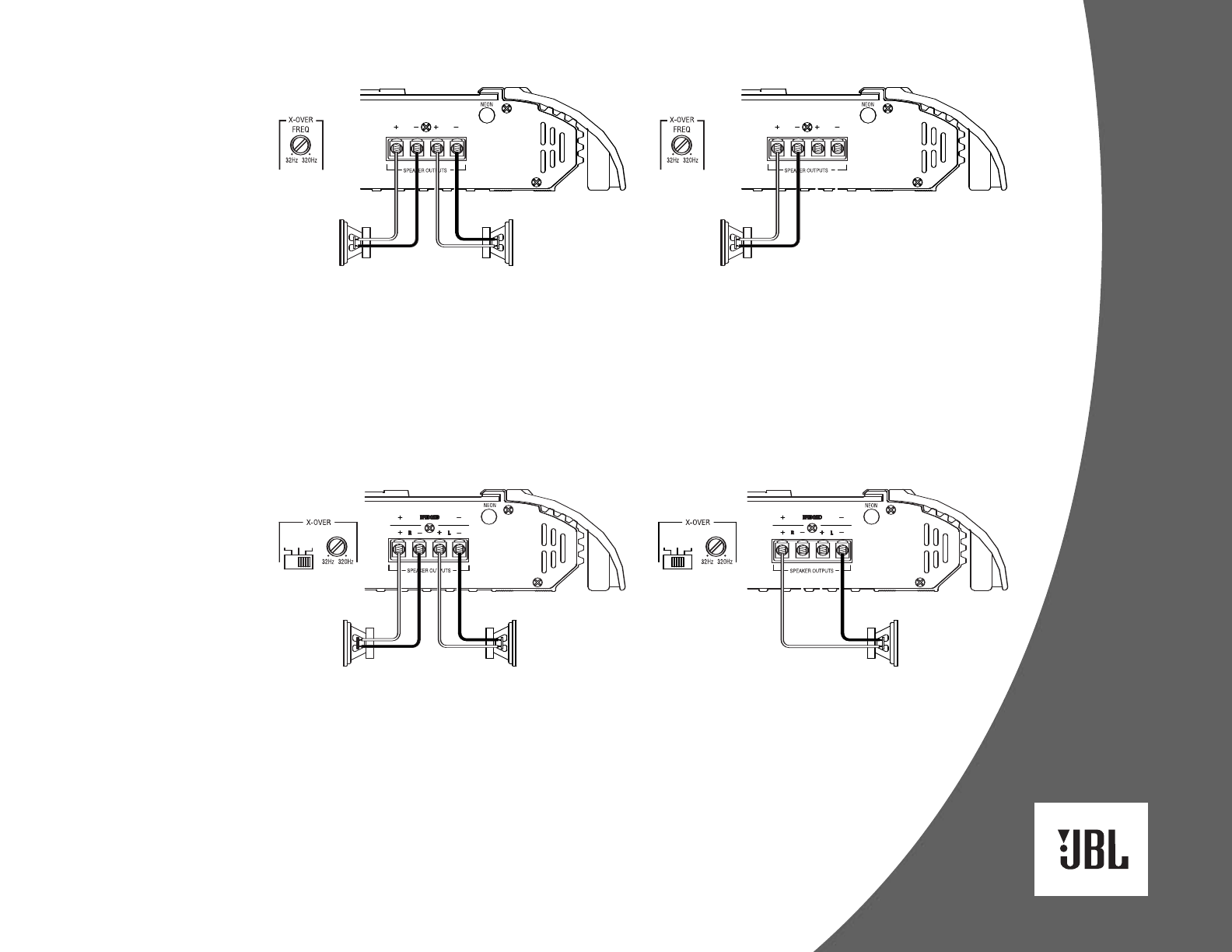
Figures 2 and 3
show how to configure the GTO
subwoofer amplifiers (models
GTO301.1
II, GTO601.1II and GTO1201.1II).
NOTE: For simplicity, Figures 2 and 3
do not show power, remote and input
connections.
NOTE: Minimum speaker load is
2 ohms.
3
GTO Amplifier
(partial end panel)
Subwoofer
–
+
FREQ
MODE
HP LP FLAT
GTO75.2
II
(partial end panel)
+
–
Subwoofer
GTO Amplifier
(partial end panel)
Subwoofer Subwoofer
+
–
–
+
Figure 2. GTO subwoofer amplifier with two woofer connections.
Figure 3. GTO subwoofer amplifier with one woofer connection.
Figure 4. GTO75.2II amplifier set up for stereo operation.
Figure 5. GTO75.2II amplifier set up for bridged-
mono operation.
APPLICATIONS – GTO75.2 II
The JBL GTO75.2II amplifier can be
set up for stereo or bridged-mono
operation, as shown in Figures 4 and 5.
NOTE: For simplicity, Figures 4 and 5
do not show power, remote and input
connections.
NOTE: Minimum speaker impedance
for stereo operation is 2 ohms.
Minimum speaker impedance for
bridged operation is 4 ohms.
FREQ
MODE
HP LP FLAT
+
–
–
+
GTO75.2
II
(partial end panel)


