


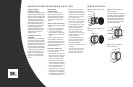

Figure 5. Mounting the tweeter using
the I-Mount flush-mounting kit.
Figure 6. Aiming the tweeter at a
desired listening position.
Figure 7. Mounting the tweeter using
the I-Mount surface-mounting kit.
Big Lug =
Small Lug =
To AMPLIFIER
SPEAKER OUTPUTS
To WOOFER
To TWEETER
Red
Blk
INSTALLATION
CONNECTIONS
1)
push in
2
)
turn
3
)
4
)
–
+
red
blk
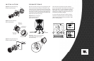
1. Slide screw up or
down to adjust
tweeter angle.
4. Securely tighten
the large hand nut.
2. Tighten nut and
washer to lock
angle settings.
3. Rotate to aim
angled tweeter
toward listener.
1
2
–
+
red
blk
Open the crossover housing by firmly squeezing the sides
of the top half and lifting it away from the bottom. Using
screws or a wire tie, mount the crossover using the holes
provided. Observing proper polarity, connect the speakers
and amplifier as shown in Figures 8A and 8B. Replace the
cover when you are finished making the connections and
adjustments (see following section).
Figure 8A. Wiring connections
on the crosssover network
(shown with cover on).
Figure 8B. Locating wiring connections
on the P552 woofer. Other woofers
are wired similarly.
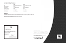
The Power Series component crossover features a
tweeter-level adjustment. The tweeter level may be set to
0dB (flat response), or it may be attenuated by approxi-
mately 3dB to suit the listener’s preference. The factory
default position is 0dB; if this is the desired setting, it is
not necessary to make any changes.
If a reduced tweeter output level is desired, carefully
remove the small plastic jumper from the pins marked
“0dB” and place it across the two pins marked “–3dB”
(refer to drawings below).
0.08mH*0.7R
L2
LP135
PTC
2R0
R1
2R0
R2
MT2.2u
C1
0.15mH*0.7R
L1
12u
C2
POWER P550C
-3dB
0dB
T+T-W+W-In+In-
-3dB
0dB
-3dB
0dB
Flat
Jumper
Jumper
–3dB