


Page 4
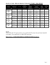
NOTES ON SUBWOOFER WIRING
• VT4880: Users may choose to wire both 2258 (18”) components in parallel to one (1)
channel of a MA-3600 or MA-5002 for (4) ohms load. In this case each amplifier
channel drives one VT4880. If two VT4880 are wired in parallel, the load is two ohms
and there will be no amplifier power headroom.
• VT4881: Users may choose to wire both coils
in a single 2256G component in parallel to
one (1)
channel of a MA-3600 or MA-5002 for (4) ohms load. In this case each amplifier
channel drives one VT4881. If two VT4881 are wired in parallel, the load is two ohms.
USERS MUST NOT WIRE THE VOICE COILS ON A 2256G (VT4881) OUT OF
POLARITY TO EACH OTHER.
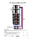
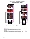
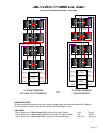
NL8: PIN 1 +
= RED CONNECTOR A & BLACK CONNECTOR A
NL8: PIN 2 +
= RED CONNECTOR B & BLACK CONNECTOR B
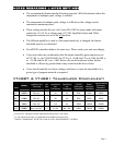
STANDARD AMPLIFICATION RACK
For those users looking to minimize amplifier rack configurations, one rack with 4 MA-5002
and 2 NL8 output circuits can power up to:
• 4 to 6 VT4889 (2 or 3 boxes per circuits AMPS: HF, MF, LF1, LF2)
OR
• 4 to 6 VT4888 (2 or 3 boxes per circuits AMPS: HF, MF, LF1, LF2)
OR
• 8 VT4887 & 4 VT4881
(4 VT4887 & 2 VT4881 per circuit AMPS: MF/HF, LF, VLF1, VLF2)
This rack would use the same input signal path from the digital controller of choice. Users
would only need to recall the appropriate DSP file on the unit.
• VT4889 or VT4888
DSP outputs: LO, MID, HIGH (stereo)
• VT4887 & VT4881
DSP outputs: SUB, LO, MID/HIGH (stereo)