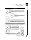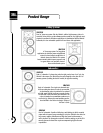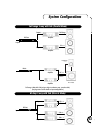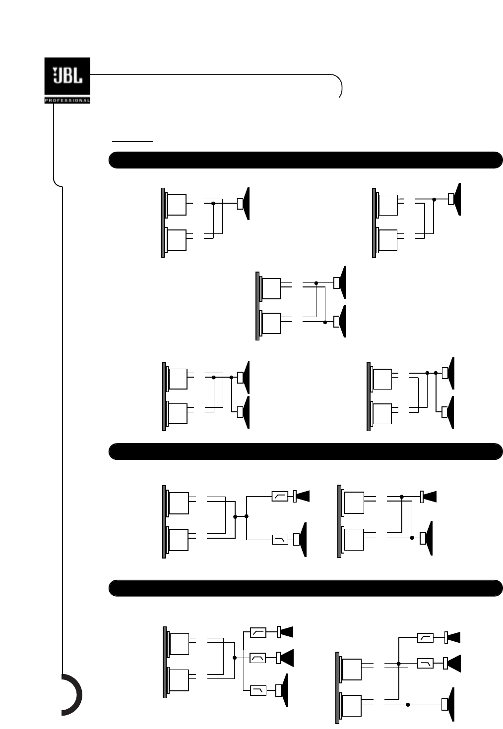
Input Configurations
Sub Connector Plate w/ NL4 MPR Inputs
SR4715/19X Discrete Mode
2-Way Connector Plate w/ NL4 MPR Inputs
In
Out
LF #2
LF #1
In
Out
LF #2
LF #1
±2
±2
±1
±1
In
Out
LF #2
LF #1
±2
±2
±1
±1
In
Out
LF
±2
±2
±1
±1
In
Out
LF
±2
±2
±1
±1
Passive Mode
Bi-Amp Mode
In
Out
In
Out
HF
LF
±2
±1
±2
±1
±2
±1
±2
±1
±2
±1
±2
±1
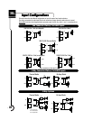
This section describes the different configurations of Input Connector Panel mode selections.
The wiring connections from the Input Panel to the transducers change when the mode selector is moved.
Please Note: Each line in the diagrams below represents a pair of wires. (E.g. both +1 and -1 connecting wires.)
10
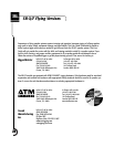
Input Configurations
3-Way Systems
Passive Mode
Bi-Amp Mode
In
Out
HF
LF
In
Out
LF
±2
±1
±2
±1
±2
±1
±2
±1
MF
HF
MF
LPF
BPF
HPF
LPF
HPF
LPF = Low Pass Filter
BPF = Band Pass Filter
HPF = High Pass Filter
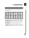
SR4718X Pin 1 Hot (as shipped) SR4718X Pin 2 Hot *
SR4715/19X Pin 1 Hot (as shipped) SRX4715/19X Pin 2 Hot *
LPF
HPF
* Units manufactured after April ‘00.
HF
LF


