


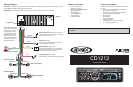
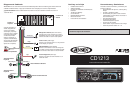

Speaker Requirements
Only connect speakers rated with a load impedance of 4 ohms. Speakers with a load impedance of less than 4
ohms could damage the unit.
Preparation
This unit is designed for installation in cars, trucks and vans with an existing radio opening. In many cases, a
special installation kit will be required to mount the radio to the dashboard. These kits are available at electronics
supply stores and car stereo specialty shops. Always check the kit application before purchasing to make sure the
kit works with your vehicle. If you need a kit but cannot locate one, call our customer support line at 1-800-323-
4815. (U.S.A. and Canada only.)
To prevent a short circuit, be sure to turn off the ignition and
remove the negative (-) battery cable prior to installation.
NOTE: If this unit is to be installed in a car equipped with an on-board
drive or navigation computer, do not disconnect the battery cable. If the
cable is disconnected, the computer memory may be lost. Under these
conditions, use extra caution during installation to avoid causing a short
circuit.
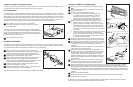
Remove transport screws.
ISO-DIN Installation
This unit has threaded holes in the chassis side panels which may be used with the original factory mounting
brackets of some vehicles to mount the radio to the dashboard. Please consult with your local car stereo shop for
assistance on this type of installation.
Remove the existing factory radio from the dashboard or
center console mounting. Save all hardware and brackets
as they will be used to mount the new radio.
Carefully unsnap the plastic frame from the front of the
new radio chassis. Remove and discard the frame.
Remove the factory mounting brackets and hardware from
the existing radio and attach them to the new radio.
CAUTION: Do not exceed M5 X 9MM screw size. Longer
screws may damage components inside the chassis.
Wire the new radio to the vehicle as outlined in the Mounting
Sleeve Installation instructions.
Mount the new radio assembly to the dashboard or center console
using the reverse procedure in step 1.
CAUTION! Be careful not to damage the car wiring.
1
2
3
4
1
2
5
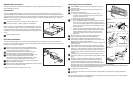
Mounting Sleeve Installation
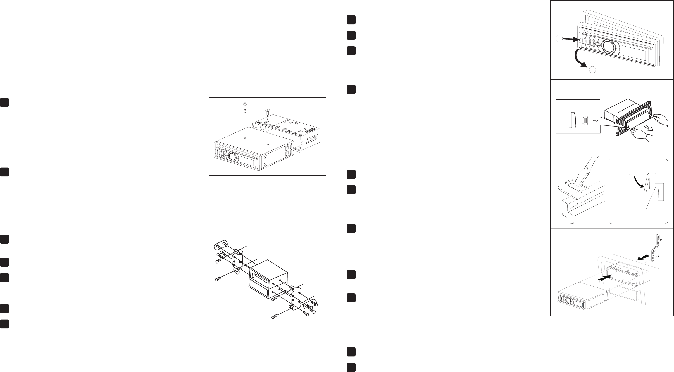
Push the REL button and remove the detachable front panel
from the chassis.
Remove the trim ring by lifting in the center and pulling it off
from either side.
Remove the mounting sleeve.
Insert the removal keys straight back until they lock. If
removal keys are inserted at an angle, they will not lock
properly to release the unit.
Slide the mounting sleeve off the chassis.
Install the mounting sleeve in the dashboard.
Check the dashboard opening size by sliding the mounting
sleeve into it. If the opening is not large enough, carefully
cut or fi le as necessary until the sleeve easily slides into the
opening. Do not force the sleeve into the opening or cause
it to bend or bow.
Locate the series of bend tabs along the top, bottom and
sides of the mounting sleeve. With the sleeve fully inserted
into the dashboard opening, bend as many of the tabs
outward as necessary to fi rmly secure the sleeve to the
dashboard.
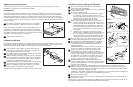
Place the radio in front of the dashboard opening so the
wiring can be brought through the mounting sleeve.
Follow the wiring diagram carefully and make certain all
connections are secure and insulated with crimp connectors or
electrical tape to ensure proper operation.
WARNING! Only connect the unit to a 12-volt power supply with
proper grounding.
After completing the wiring connections, attach the front panel
and turn the unit on to confi rm operation (vehicle ignition switch
must be on). If the unit does not operate, recheck all wiring until
the problem is corrected. Once proper operation is achieved,
turn the ignition switch off and proceed with fi nal mounting of the
chassis.
Carefully slide the radio into the half-sleeve, making sure it is
right-side-up until it is fully seated and the spring clips lock it into
place.
Attach one end of the perforated support strap (supplied) to
the screw stud on the rear of the chassis using the hex nut
provided. Fasten the other end of the perforated strap to a
secure part of the dashboard, either above or below the radio,
using the screw and hex nut provided. Bend the strap, as necessary, to position it.
CAUTION: The rear of the radio must be supported with the strap to prevent damage to the dashboard from
the weight of the radio or improper operation due to vibration.
Re-attach the decorative trim ring.
Re-attach the front panel to the chassis and test radio operation by referring to the operating instructions
for the unit.
NOTE: For proper operation of the CD/MP3 player, the chassis must be mounted within 20° of horizontal. Make
sure the unit is mounted within this limitation.
a.
b.
a.
b.
1
2
3
4
5
DASHBOARD
TAB
2
1
Step 3
Step 4b
Steps 8-9
6
7
8
9
10
11
Removal Key
Step 1