VM8013
3
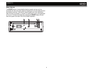
WIRING
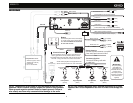
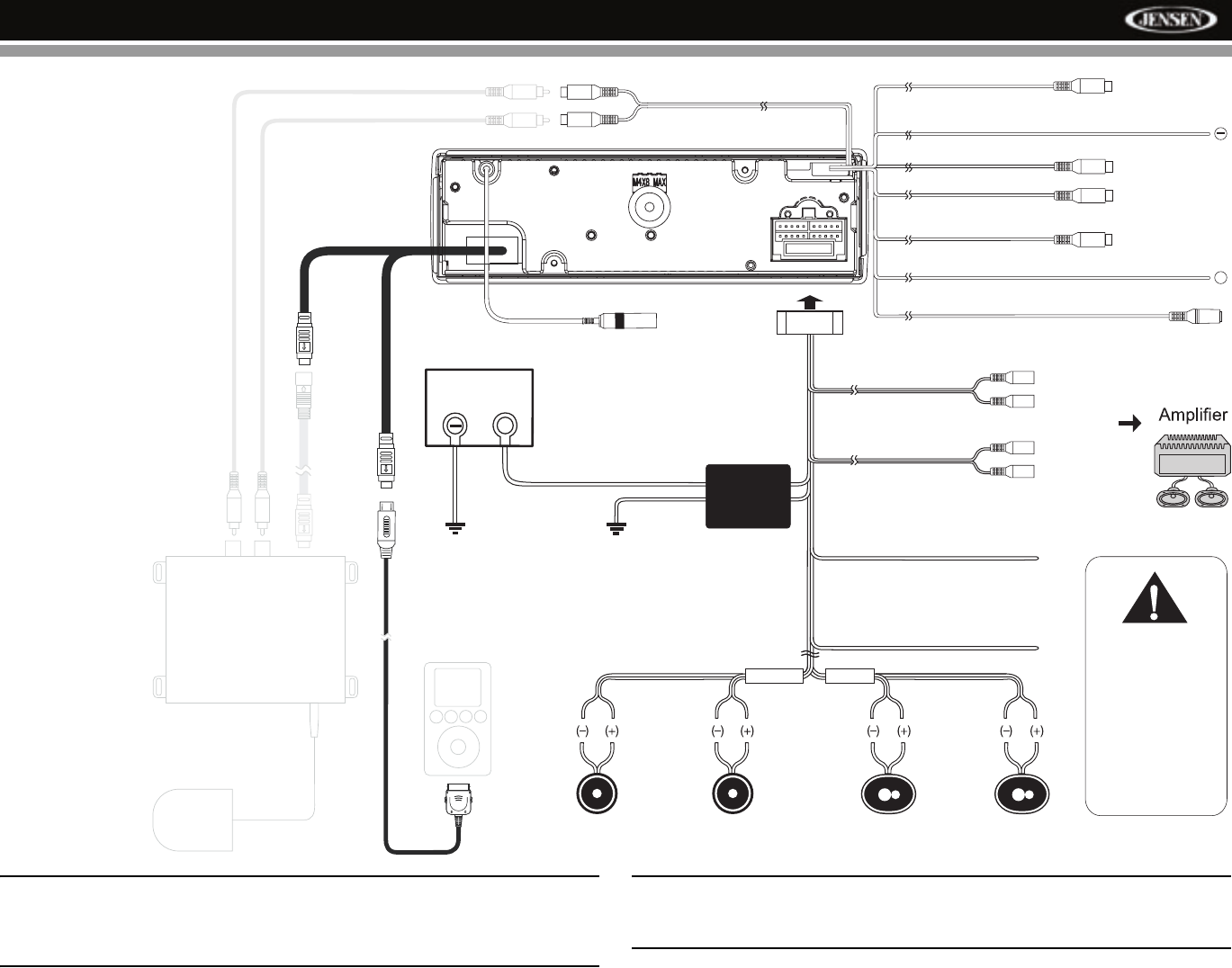
NOTE: The amplifier in this radio is only designed for use with four
speakers. Never combine (bridge) outputs for use with two speakers.
Never ground negative speaker leads to chassis ground. Failure to
wire exactly as shown may cause electrical damage to the radio.
NOTE: Only connect speakers with a nominal impedance of 4 ohms.
Speakers with a load impedance less than 4 ohms could damage the
unit.
(Yellow)
(Yellow)
(Blue)
(Yellow)
Purple
Purple/Black
Stripe
Gray
Gray/Black
Stripe
White/Black
Stripe
White
Green/Black
Stripe
Green
Left Speaker
(Front)
Right Speaker
(Front)
Left Speaker
(Rear)
Right
Speaker
(Rear)
Blue
Red
Front Line out
R (Red)
L (White)
Black
Power Antenna
Connect to power antenna or amplifier.
If not used, tape bare end of wire.
Accessory/Ignition
Connect to existing radio wire
or radio fuse.
Rear Line out
R (Red)
L (White)
Gray
Yellow
Black
Subwoofer Out
Parking/Active Low Level Input
(Pink)
Camera In
SAT R (Red)
Video Out 1
SAT L (White)
Video Out 2
Fuse (15A)
Camera/Active High Level Input (Green/White)
SWC (Steering Wheel Control)
Chassis Ground
Battery
)
-
()
(
+
Connect the black wire to the factory ground wire. If a
factory ground wire is not provided, locate a clean,
unpainted metal part of the dash and secure the ground
wire with a "ring" terminal and a sheet metal screw.
Connect the yellow wire to the battery
or 12 volt power source that is always
live. This wire MUST be connected
for the radio to work.
FILTER
BOX
IMPORTANT!
The pink parking
wire MUST be
connected to the
switched side of the
parking break
circuit (the part that
becomes grounded
when the brake is
applied).
FRONT
REAR
Antenna
(Requires PAC SWI-PS InterfaceAdapter)
+
NOTE: Video playback not supported for all
iPods. See iPod section for more information.
SAT BUS
IPOD BUS
iPod
(Sold Separately)
jLink iPod Cable
(Included)
Compatible SAT Tuners:
1. XMD1000 (requires XMC or
XMDJEN100 Cable Kit)
2. CNP2000UC
3. SC-C1 and SIRJEN2


