


3
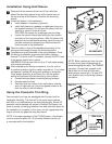
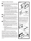
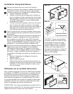
Installation Using Half-Sleeve
Remove the four screws at the front of the radio that
attach the mounting sleeve to the radio chassis (two at
the top and two at the bottom). Remove the mounting
sleeve.
Install half-sleeve in the dashboard.
Install adapter if necessary (optional).
Install half-sleeve into adapter or dashboard (use only
the supplied screws). Do not force the sleeve into the
opening or cause it to bend or bow.
CAUTION! Be careful not to damage the car wiring.
Locate the series of bend-tabs along the top, bottom
and sides of the mounting sleeve. With the sleeve fully
inserted into the dashboard opening, bend as many of
the tabs outward as necessary so that the sleeve is
fi rmly secured to the dashboard.
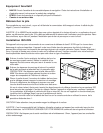
Place the radio in front of the dashboard opening so the
wiring can be brought through the mounting sleeve.
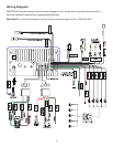
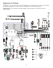
Complete wiring as illustrated in the wiring diagram. Once
the wiring is complete, reconnect the battery negative
terminal. If there is no ACC available, connect the ACC lead
to the power supply with a switch.
WARNING! Only connect the unit to a 12-volt power supply
with proper grounding.
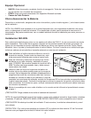
After completing the wiring connections, turn the unit on
to confi rm operation (ignition switch must be on). If unit does
not operate, recheck all wiring until problem is corrected.
Once proper operation is achieved, turn off the ignition
switch and proceed with fi nal mounting of the chassis.
Connect wiring adapter to existing wiring harness.
Connect antenna lead.
Carefully slide the radio into the half-sleeve, making
sure it is right-side-up. Use the supplied screws to at-
tach the radio to the half sleeve.
Using the Cosmetic Trim Ring
Two cosmetic trim rings are packaged with the head unit for
installation fl exibility. This unit will fi t into most import dashes
with little or no modifi cation to the dash board/cavity. Some US
domestic vehicle dashes will accept a Double-DIN chassis, but
there is usually a small gap between the radio and dash piece af-
ter installation is complete. In this case, use the appropriate trim
ring to conceal any gaps that may be present.
NOTE: For proper operation of the CD/DVD player, the chassis
must be mounted within 30° of horizontal. Make sure the unit
is mounted within this limitation.
a.
b.
c.
a.
b.
c.
1
2
3
4
5
DASHBOARD
TAB
Step 2-b
Step 2-c
Step 5-c
MOUNTING
SLEEVE
TRIM RING
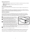
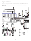
NOTE: When replacing a fuse, be sure
to use correct type and amperage to
avoid damaging the radio. The VM9223
uses one 10 amp fuse, located in the
black fi lter box in-line with the main
wire harness as well as a 15 amp ATC
fuse located next to the wiring harness
connector.