


VM9510
4
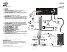
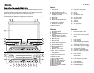
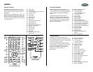
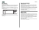
Wiring
Wiring Connections
1. TV TUNER
2. ANTENNA
3. POWER ANTENNA WIRE (Blue) – Connect to a motorized (power)
antenna and/or to a remote turn-on lead for an amplifier.
4. CONSTANT POWER WIRE (Yellow) – Connect the 12V PLUS constant
power wire to a live 12 volt wire in the vehicle. Before making a connection,
check that the wire you intend to connect it to is always live, even when the
car’s ignition is turned off. If a live wire is not found, route the wire to the
car’s fuse block and connect it to a live circuit there.
5. GROUND WIRE (Black) – Securely fasten the Ground wire to a grounded
metal part of the car’s chassis. If you cannot find an existing bolt or screw
to fasten it to, drill a hole in the metal and secure it with a screw. To ensure
a good ground, remove any paint or grease from areas where the wire will
contact the surface.
6. PARKING (Pink) – Connect to negative parking brake wire. This wire
MUST BE connected in accordance with federal, state and local laws. It is
the end-user’s responsibility to make sure this wire is connected properly.
7. ACC POWER WIRE (Red) – Connect to a +12 volt circuit that is only live
when the ignition is on. The best connection point is at the car’s fuse block
at the “RADIO” or “ACCESSORY” identified terminals.
8. LEFT FRONT SPEAKER (white, white/black)
9. RIGHT FRONT SPEAKER (gray, gray/black
10. LEFT REAR SPEAKER (green, green/black)
11. RIGHT REAR ( + ) SPEAKER (violet, violet/black)
12. FRONT AND REAR RCA OUTPUTS
13. CENTER RCA OUTPUT (Gray) – The center output must be connected to
an external amplifier for 3D or 6-CH mode.
14. SUBWOOFER RCA OUTPUT (Blue) – The subwoofer output is available
in all sound/audio modes.
15. DEDICATED DVD OUTPUT – Video output for rear screen and left/right
audio output for headphones.
16. AV1 INPUT
17. AV2 INPUT
18. VIDEO OUT (Yellow) - V. SEL output for rear screen.
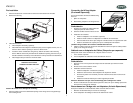
Replacing the Fuse
When replacing a fuse, be sure to use correct type and amperage to avoid
damaging the radio. The VM9510 uses one 10 amp AGC fuse, located in the
black filter box in-line with the main wire harness.
Reconnecting the Battery
When wiring is complete, reconnect the battery negative terminal.
Gray/Black (-)
Gris / Negro (-)
Gris / Noir (-)
Gray / Gris / Gris (+)
9
White/Black (-)
Blanco/Negro (-)
Blanc/Noir (-)
White / Blanco / Blanc (+)
Violet/ Violeta /Violet (+)
8
10
11
Green / Verde / Vert (+)
Green/Black (-)
Verde/Negro (-)
Vert/Noir (-)
Violet/Black (-)
Violeta/Negro (-)
Violet/Noir(-)
1
Gray
Gris / Gris
Black
Negro / Noir
Front
Frente
Avant
Rear
Posterior
Arrière
12
3
Blue /Azul / Bleu
7
Black / Negro / Noir
4
+
Yellow /Amarillo / Jaune
6
Pink / Rosa / Rose
13
14
16
17
15
Red / Rojo / Rouge
TO RADIO-
1
2
3
4
ANT
OP
T
I
ON
A
L
D
I
V
E
RS
I
T
Y
VM9510
TVTuner
Reciever
Antenna Included
la Antena Incluyó
l'antenne a Inclus
18
10A
5
FIL TER &
FUSE BOX
2