


6 | JL Audio - 500/1v2 Owner’s Manual
7
IMPORTANT
!
You cannot use the turn-on output to turn on
processors that are in the signal path before the
500/1v2. (Signal will not pass through most
processors when they are not powered up,
meaning that the amplifier will not turn on
until that processor is active).
AMPLIFIER INPUT SECTION
The 500/1v2 employs a differential-balanced
input topology that provides the user with a high
degree of input flexibility while retaining superior
noise rejection. This type of circuit also allows
the 500/1v2 to accept high-voltage inputs from
factory source unit outputs without excessive
distortion or noise problems.
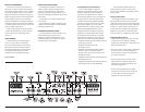
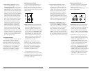
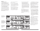
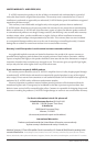
+12VDC Ground Remote Preamp Output Section
Infrasonic Filter
“Q” Center Freq. Boost (dB)
Amp LP Filter
Advanced
Bass
Control
Amplifier Input Section
Subwoofer Output
MONO OUTPUT ONLY
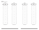
Left Output Right Output Left Ch. Right Ch.Filter Freq. (Hz) Filter Freq. (Hz)Infrasonic Freq. (Hz) Remote Bass Port
Full Range
|
Amp Filter
|
Out Filter
Output Mode Filter Slope Mode
Mode
|
Slope
Input Voltage Input Sens. Signal Sensing
12dB
|
24dB
Filter Mode
LP
|
HP
Bass EQ
Off
|
On
Off
|
12dB
|
24dB Low
|
High Off
|
OnOff
|
On
40
45
55
65
80
100
200 15
18
22
30
45
55
60 40
45
55
65
80
100
200
0.5
0.7
1.1
1.6
2.7
4.3
20
25
30
40
60
75
80 0
+4
+10
+13
+15
500/1v2
Monoblock Subwoofer Amplifier
1) Input Connections: A standard left/right pair
of RCA type jacks is used for input on
the 500/1v2. You may run a stereo or a mono
signal into the inputs of the amplifier. The
amplifier’s input section automatically sums
stereo signals to mono for the internal
amplifier section and for the “LP” “Filter
Mode” of the “Preamp Output” section.
IMPORTANT
!
If you plan to use the “Preamp Output” in
“Full-Range” or “HP” mode to feed a stereo
amplifier, you must connect a stereo signal to
the input of the amplifier. A mono signal into
the amplifier will result in a mono signal out of
the preamp output. (It’s a great amplifier, but it
doesn’t do magic).
The amplifier will operate with only one input
connection (left or right), but will require an
increase in input sensitivity to overcome the loss
of signal. If a mono input signal is to be run, we
recommend that you use a “Y-adaptor” like the
JL Audio ECS model XB-CLRAICY-1F2M to split
the mono signal into both inputs of the amplifier.
2) Input Voltage Range: A wide range of
signal input voltages can be accommodated
by the 500/1v2’s input section (200mV – 8V).
This wide range is split up into two sub-
ranges, accessible via switches located in the
“Amplifier Input Section” of the amplifier.
The “Low” position on the “Input Voltage”
switch selects an input sensitivity range
between 200mV and 2V. This means that
the “Input Sens.” rotary control will operate
within that voltage window. If you are using
an aftermarket source unit, with conventional
preamp-level outputs, this is most likely the
position that you will use. The “High” position
on the “Input Voltage” switch selects an input
sensitivity range between 800mV and 8V. This
is useful for certain high-output preamp level
signals as well as speaker-level output from
source units and small amplifiers. To use
speaker-level sources, splice the speaker output
wires of the source unit or small amplifier
onto a pair of RCA cables or plugs or use the
JL Audio ECS Speaker Wire to RCA adaptor
(XB-CLRAIC2-SW).
IMPORTANT
!
The output of the amplifier will decrease
for a given input voltage when the “Input
Range” switch is placed in the “High” position.
Conversely, the output will be higher with
the switch in the “Low” position. While this
may sound counter-intuitive, it is correct
as described.
TURNON OPTIONS
The 500/1v2 can be turned on and off using
two different methods:
1) A conventional +12V remote turn-on lead.
2) A signal sensing turn-on circuit.
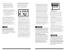
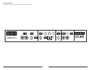
+12VDC Ground Remote Preamp Output Section
Infrasonic Filter
“Q” Center Freq. Boost (dB)
Amp LP Filter
Advanced
Bass
Control
Amplifier Input Section
Subwoofer Output
MONO OUTPUT ONLY
Left Output Right Output Left Ch. Right Ch.Filter Freq. (Hz) Filter Freq. (Hz)Infrasonic Freq. (Hz) Remote Bass Port
Full Range
|
Amp Filter
|
Out Filter
Output Mode Filter Slope Mode
Mode
|
Slope
Input Voltage Input Sens. Signal Sensing
12dB
|
24dB
Filter Mode
LP
|
HP
Bass EQ
Off
|
On
Off
|
12dB
|
24dB Low
|
High Off
|
OnOff
|
On
40
45
55
65
80
100
200 15
18
22
30
45
55
60 40
45
55
65
80
100
200
0.5
0.7
1.1
1.6
2.7
4.3
20
25
30
40
60
75
80 0
+4
+10
+13
+15
500/1v2
Monoblock Subwoofer Amplifier
To select between the two modes there is a
switch, marked “Signal Sensing”, located in the
“Amplifier Input Section” of the front panel.
1) Conventional Remote Turn-On Method:
uses a conventional +12V remote turn-on
lead, typically controlled by the source unit’s
remote turn-on output. The amplifier will
turn on when +12V is present at its “Remote”
input and turn off when +12V is switched
off. If a source unit does not have a dedicated
remote turn-on output, the amplifier’s turn-
on lead can be connected to +12V via a switch
that derives power from an ignition-switched
circuit. To use this method, select “Off” on
the “Signal Sensing” switch in the “Amplifier
Input Section”. The 500/1v2’s “Remote”
turn-on connector is designed to accept 12
AWG – 8 AWG wire. 12 AWG is more than
adequate for this purpose. To connect the
remote turn-on wire to the amplifier, first back
out the set screw on the top of the amplifier,
using the supplied hex wrench. Strip 1/2
inch (12mm) of wire and insert the bare wire
into the receptacle on the front panel of the
amplifier, seating it firmly so that no bare wire
is exposed. Smaller wire than 12 AWG can be
used, but it may be necessary to strip 1 inch
of insulation from the wire and fold the bare
wire in half prior to insertion. While holding
the wire in the terminal, tighten the set screw
firmly, taking care not to strip the head of the
screw and making sure that the wire is firmly
gripped by the set screw.
2) Signal Sensing Turn-On Method: A valuable
feature of the 500/1v2 is its ability to be turned
on and off by the presence or lack of signal at
its audio inputs. This allows you to operate the
amplifier without having to locate a remote
turn-on lead at the source unit. This can be
very useful if interfacing the amplifier with
some OEM source units that do not have
conventional turn-on leads.
IMPORTANT
!
The sensitivity of the signal sensing turn-on
circuit has been designed for high-level
(speaker level) signals, not for low-level
(preamp level) signals. Using this feature with
low-level (preamp level) signals is not
recommended. We do not recommend this
method of turning the amplifier on and off as a
default. Whenever possible, use the
conventional remote turn-on lead method. The
signal sensing circuit is designed to detect
midrange frequency signal presence. If the
signal feeding the amplifier is not full-range
(for example, if there is an active low-pass
crossover in line before the amplifier), this
circuit will not operate properly.
To activate the signal sensing turn-on feature,
place the “Signal Sensing” switch in the “On”
position. This should only be done if there is
no conventional turn-on lead connected to the
amplifier’s “Remote” connector. When in the
“On” position, the signal sensing circuit will
monitor the audio input signal and turn the
amplifier on when signal is present. After about
25 seconds of no signal, the amplifier will shut off.
Turning on other amplifiers in signal sensing
mode: When the signal sensing circuit is turned
on, the “Remote” Connector on the amplifier
may be used as a remote turn-on source for other
amplifiers in the system. +12V will be present
at the connector when the amplifier turns on in
signal sensing mode and will not be present when
the amplifier turns off.