


When a pair of channels are bridged, they
will deliver 150W x 1 into a 4 ohm load or
90W x 1 into an 8 ohm load. Operating a
pair of bridged channels into a load lower
than 4 ohms is not recommended.
Because a bridged pair of channels requires
that both channels receive input, you need to
connect both left and right inputs to the source
unit. Connection of only one input will result in
reduced power output, increased distortion and
can cause the amplifier to overheat.
Do not do this!
When the A2150 operating in bridged mode,
the output will be in mono (only one channel).
This mono channel can contain right channel
only information, left channel only information
or the sum of the information from both the
right and left channels. In order to achieve one of
these options, configure the inputs to that pair of
channels in one of these two ways:
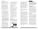
1) Left Channel Only or Right Channel Only
Information: If you wish to send a left-only or
right-only signal the A2150, use a “Y-Adaptor”
to split the single channel signal into both left
and right RCA inputs. This option is useful
when using one A2150 to drive left channel
speakers only and the other A2150’s channels
to drive right channel speakers only.
2) Left + Right Channel Information:
When bridged and fed by a stereo input, the
A2150’s channels will automatically combine
the left and right channels into a summed
mono (left + right) channel. This option is
useful when using the A2150 channels to
drive a subwoofer system or a summed mono
center channel.
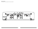
AMPLIFIER STATUS INDICATOR LIGHTS &
PROTECTION CIRCUITRY
There are two status indicator lights on the
input / control end of the amplifier.
1) “Power” (Green): lights to indicate that the
amplifier is turned on and operating normally.
2) “Protect” (Red): Indicates that the amplifier
protection circuitry has been activated to
prevent product failure due to a short-circuit
or a dangerously low impedance connected
to the amplifier output(s). Connecting the
speaker outputs to an impedance lower than
2 ohms stereo (4 ohms bridged) will cause
this protection mode to activate. When this
protection mode is activated, the amplifier will
reduce it maximum power output to protect its
circuitry, which will manifest itself as increased
distortion. When the problem is corrected, the
amplifier will return to normal operation.
Advanced Rollback Thermal protection
Unlike conventional thermal protection
systems, which shut down an amplifier when it
overheats, this system protects the amplifier by
gradually reducing power output if the amplifier’s
safe operating temperature is exceeded. The
amplifier will continue to operate and return
to normal power output once its temperature
returns to a normal range.
JL AUDIO A2150 9
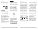
BASS BOOST CONTROLS
1) “Bass Boost”: This switch allows the user to
activate a 6 dB boost centered at 48 Hz.
When the “Bass Boost” is activated, the inputs
to “CH 1 (Left)” and “CH 2 (Right)” are
summed to create a mono signal. The “Filter
Mode” switch in the “Channel 1 & 2” section
must be in the “LP” position for the bass boost
to be functional.
2) “ Remote Bass Port”: This port allows you to
connect an optional remote boost knob (sold
separately as JL Audio Model RBC-1) that can
be mounted in the front of the vehicle. With
the RBC-1 connected, the boost is no longer
limited to 0 or +6 dB, allowing a variable
range of 0 to +12 dB of boost to be selected.
PREOUTS
The A2150 incorporates a pass-through
preamp output section, so that additional
amplifiers can be easily added to the system. The
preamp output delivers the same signal that is
connected to the A2150’s inputs.
The preamp output signal is not affected by the
“Bass Boost” processing selected for the amplifier
or by any crossover filter selected (if the input
signal is full-range, the preamp output will be
full-range).
The signal level of the “Preamp Output” is
line-level (low voltage), regardless of the position
selected in the A2150’s “Input Voltage” switch.
An additional amplifier connected to these
preamp outputs should have its input voltage
switch set to the “Low” position.
SPEAKER OUTPUTS
The A2150’s speaker outputs are designed to
accept 16 AWG - 8 AWG wire.
The A2150 is designed to deliver power into
speaker loads equal to or greater than 2 ohms
when using a “stereo” configuration and speaker
loads equal to or greater than 4 ohms when using
a “bridged” configuration.
Speaker loads below 2 ohms nominal per
channel in stereo or below 4 ohms nominal
bridged mono are not recommended and may
cause the amplifier to initiate a protection
mode which reduces power output.
BRIDGING CONSIDERATIONS
Bridging is the practice of combining the
output of two amplifier channels to drive a single
load. When bridged, each channel produces
signals of equal magnitude, but opposite polarity.
The combined output of the two channels
provides twice the output voltage available from
a single channel. The A2150 has been designed
for bridging of its channels without the need for
input inversion adaptors.
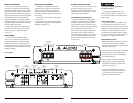
To bridge the A2150’s two channels, use the
“CHANNEL 1 +” and “CHANNEL 2 –”
speaker connectors only (the “CHANNEL 1 –”
and “CHANNEL 2 +” remain unused). When
bridged, the A2150 will deliver optimum power
into a 4 ohm load.
8 JL AUDIO A2150