


6 | JL Audio - C3-525 Owner’s Manual
CONVERTIBLE COMPONENTS
C3ConvertibleComponentsgiveyoutheoption
ofinstallingthespeakersasseparatecomponent
speakersystemsorascoaxialsystems(tweeters
mountedontothecenterofeachwoofer).
Note: If the C3 system is to be used in a coaxial
configuration, the phase plugs must be removed to
accept the tweeter and tweeter post.
Component System Set-Up
TheComponentconfigurationoftheC3-525
isachievedbywiringthetweetertothecrossover
separatelyandinstallingtheincludedphaseplugs
ontothecenterofeachwoofer.The woofers are
factory-packaged in the component system
configuration with phase plugs installed.
Thephaseplugsattachtothewoofersusinga
simplebayonet(twistandlock)mechanism.
Toremovethephaseplugs,simplyapply
downwardpressurewithyourthumbandindex
fingerandtwist1/4turncounteclockwiseuntil
released.Thenpullthephaseplugoffthereceiver.
Toreattachthephaseplugs,alignthetwo
tabsontheinsideofeachphaseplugwiththe
groovesontheouterdiameterofthereceiver
inthecenterofthewoofer.Withthesealigned,
slidethephaseplugdownintoplaceuntilit
stops,applyinggentlepressure.Tolock,push
downfirmly/evenlyontheplugwiththumband
indexfingerandturn1/4turnclockwise.
Forwoofermountinginstructions,pleaserefer
toPage8ofthisManual.Forseparatetweeter
mountinginstructions,pleaserefertoPages12-13of
thisManual.
Coaxial System Set-Up
TheCoaxialconfigurationoftheC3-525is
achievedbyinstallingatweeterontothecenterof
eachwooferusingthesuppliedcoaxialtweeterposts.
First,removethephaseplugsfromthewoofers(if
present)bypushingdownfirmly/evenlyontheplug
withthumbandindexfingerandturning1/4turn
counter-clockwisetounlockandremove.Thephase
plugswillnotbeusedincoaxialconfigurationand
shouldbesetasideforpossiblefutureuse.
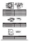
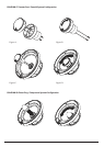
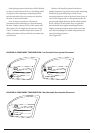
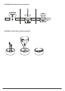
Next,routethetweeter’sPositive(+)and
Negative(-)wireleadsthroughthecenterofthe
coaxialtweeterpostfromthelargetweeter-cupend
andoutthesmallerend(SeeFigureA).Thetweeter
mountstothecoaxialtweeterpostusingasimple
bayonet(twistandlock)mechanism.Toattachthe
tweetertothepost,observetheindentedlocking
slotsontheouteredgeofthetweeterbodyandalign
thesewiththetabsvisibleontheinsidewallsofthe
tweetercupportionofthetweeterpost.Thetweeter
shouldslideintoplaceeasilyandcanthenbelocked
bypushingdownonthetweeterandgivingitasmall
clockwiseturn(SeeFigureB).
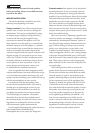
Withthetweeterinstalledintothetweeterpost,
connectthePositive(+)redwireleadonthetweeter
tothelargermaleconnectiontabinthewoofer’s
center,followedinthesamemanner,bythe
Negative(-)blackleadtothesmallerconnectiontab.
(SeeFigureC).
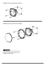
Now,notethetwotabsontheinsideofthebottom
endofthetweeterpost.Alignthesetabstothe
channelsvisibleonoppositesidesofthereceiverin
thewoofer’scenter.Whiletuckingthewiresintothe
tweeterpost,slidethetweeterpostdownintoplace
untilitstopsandisreadytobelocked.Tolock,push
downfirmly/evenlyonthetweeterpostwiththumb
andindexfingerandturn1/4turnclockwise.
(SeeFigureD).
Forwoofermountinginstructions,pleasereferto
Page11ofthisManual.