


10 | JL Audio - C5-653 Owner’s Manual
11
coveredwithaprotective,flexiblePVCsleeveandthen
runthroughthedoorjamb.Makesurethatthewires
willcleardoorhingesandotherstructuresinthedoor.
Ifyouareunsureaboutanypartofthisprocess,please
contactyourJLAudiodealerforinstallationhelp.
Selectanevensurface.Tighteningaspeakeronto
anunevensurfacecandamageit.Carefullymeasure
andmarkthe“mountingholediameter”outlineinthe
selectedlocationusingthedimensionslistedonpage2.
Beforedrillingorcuttingonyourinteriorpanels,usea
utilityknifetocutanyfabric,vinylorleatherfromhole
locations.Thesematerialscaneasilybesnaggedbya
drillorasaw,causingdamagetothepanelandpossible
bodilyinjury.Drillapilotholeinthecenterofthe
proposedspeakermountinghole.Then,usingasaber
sawwithanappropriateblade,makethecircularcut
outforthespeaker.Fileanyroughedges.
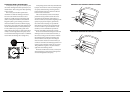
Aftercuttingthehole,checktoseethatthespeaker
framefitsintoitsmountingholecleanly.Donot
forcetheframeintoaholethatistoosmall.Once
thespeakerisinplace,usetheholesonthespeaker’s
grilletraytomarkthepanelwherethefourmounting
screwswillbepositioned,asshowninDiagramF.
Removethespeakeranddrill3/32-inch(2.4mm)
holesateachmark.Insertthe#6mountingclipswith
theflatsidetowardsthespeaker.Connectthespeaker
wires,observingcorrectpolarity,andsecurethe
frameadaptor,speakerandgrilletraytothepanelby
evenlytighteningbyhandtheprovided#6x1.25inch
(32mm)mountingscrews.Makesurethemidrange
driverissecuredsothatairdoesnotleakaround
themountingflange.Airleakswillcauseasevere
degradationinsoundquality.Sealanyairleakswith
anautomotive-gradesealantmaterial.
Breakoffsmallpiecesofthesuppliedbutyladhesive
puttyandplacethemontheinsideofeachgrilletray.
Thisadhesivewillholdthegrillemeshinsertinplace
firmlyandpreventrattling.Insertthegrillemesh
insertintothegrilletray,squeezinggentlyaroundits
edgeuntilitseatsfirmlyintothetray.Finally,attach
theself-adhesiveJLAudiologobadgetothegrille
meshinsert.
Youmayalsochoosetoinstallthemidrangedrivers
usingtheFrameAdaptorswithnogrilletray.Thiscan
beusefulforapplicationswhereacustomgrilleisbeing
fabricatedandwillresultinasmalleroverallmounting
diameterthanthestandardtab-mountsystemas
showninDiagramGonpage11.
WARNING
!!
Double check the clearance for both speakers
before proceeding. Many cars are different from
one side to the other!
MIDRANGE INSTALLATION
Themidrangedriversshouldbeinstalledinoneof
thefollowingwaysdependingonlocation:
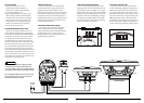
Factory Location:Followthesamewiringprocedures
outlinedforthewooferinstallation.
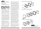
TheC5-400cmhasbeendesignedtoinstall,without
modifications,intomostvehiclesthataccepta4-inch
(100mm)speaker.Mostfactory4-inchspeakersuse
fourmountingscrewswhichwilllineupwiththe
mountingholesonyourwoofers.Inmostfactory
locations,itwillbenecessarytousethesuppliedFlush
MountAdaptorRingsasshownintheDiagramEon
page11.
Usethesuppliedmountingclipsunlessthefactory
holesalreadyfeaturethreadedinserts.Hand-tighten
thescrewsevenlytoavoidbendingthespeakerframe!
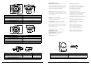
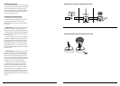
Somevehicleswhichaccepta4-inch(100mm)
speakeruseatwo-holemountingsystem.Thiscanbe
easilyaccommodatedbybreakingofftwoofthetabsas
showninthediagramatthetopofthispage.Allfour
mountingtabsareperforatedtopermittheirremoval.
Bendeachunneededtabbackandforthuntilitbreaks
off.Pleasebecarefulinhandlingthespeakerafter
breakingoffthetabsastheremaybesharpedges.
Custom Location:Forcustom-mounted
applications,breakoffallfourmountingtabsand
usethesuppliedFrameAdaptorsasshowninthe
diagramsonpage11.TheseFrameAdaptorspermit
forasmalleroveralldiameterwhencustommounting
thespeakersandmustbeusedinordertoinstallthe
suppliedgrilles.
Runspeakerwiretothedesiredmountinglocations.
Ifyouarerunningwiresintoadoor,useexisting
factorywiringbootswheneverpossible.Ifyouare
drillingnewholes,filetheiredgesandinstallrubber
grommetsintoeachhole.Wiresshouldthenbe
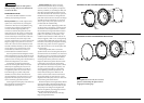
DIAGRAM E: FACTORY LOCATION WOOFER INSTALLATION
DIAGRAM F: CUSTOM LOCATION WOOFER INSTALLATION
DIAGRAM G: CUSTOM LOCATION WOOFER INSTALLATION
WARNING
!!
Hand-tighten the screws evenly in a criss-cross
pattern to avoid bending the speaker frame or
stripping the mounting clips.