


Do not attempt to “bridge”the outputs of this
amplifier with the outputs of a second amplifier,
including an identical one.
Using the e1200 for Left Channel Only or Right
Channel Only Information:
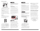
If you wish to send a Left-only or Right-only
signal to the e2150, use a “Y-Adaptor” to split the
single channel signal into both left and right RCA
inputs (or parallel-connect both positive and both
negative high-level input connections to a single
channel source signal).This option is useful when
using one e2150 to drive the left channel speakers
only and another e2150 to drive right channel
speakers only.
When parallel-connecting both positive and both
negative high-level input connections as described
above,make sure to connect negative (–) wires to
negative (–) wires and positive (+) wires to
possitive (+) wires.
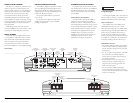
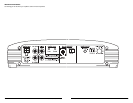
AMPLIFIER STATUS INDICATOR LIGHTS /
PROTECTION CIRCUITRY
There are two status indicator lights on the
input / control end of the amplifier:
1) “Power” (Green): lights to indicate that the
amplifier is turned on and operating normally.
2) “Protect” (Red): lights or flashes to indicate
that the amplifier protection circuitry has been
activated to prevent product failure.
a) If the red “Protect” indicator lights steadily
(without flashing), the amplifier has exceeded its safe
operating temperature.This causes the amplifier to
shut off in order to protect its circuitry. When the
IMPORTANT
!
IMPORTANT
!
amplifier’s temperature drops to a safe level, the red
“Protect” indicator will shut off and the amplifier
will return to normal operation.
b) If the red “Protect” indicator flashes
intermittently,the protection circuitry has detected a
short-circuit or a dangerously low impedance
connected to the amplifier output(s). Connecting the
speaker outputs to an impedance lower than 2Ω will
cause this protection mode to activate.The amplifier’s
output may cycle on and off when this protection
mode is activated.When the problem is eliminated,
the amplifier will return to normal operation.
SERVICING YOUR JL AUDIO AMPLIFIER
If your amplifier fails or malfunctions, please
return it to your authorized JL Audio dealer so
that it may be sent in to JL Audio for service.
There are no user serviceable parts or fuses
inside the amplifier.The unique nature of the
circuitry in the JL Audio amplifiers requires
specifically trained service personnel. Do not
attempt to service the amplifier yourself or
through unauthorized repair facilities.This will not
only void the warranty, but may result in the
creation of more problems within the amplifier.
If you have any questions about the installation or
setup of the amplifier not covered in
this manual, please contact your dealer or the
JL AUDIO Technical Department for assistance:
(954) 443-1100
9:00 AM – 5:30 PM Eastern Time,
Monday – Friday
JL AUDIO e1200 9
BASS BOOST CONTROLS
1) Bass Boost: This switch allows the user to
activate a 6 dB boost centered at 48 Hz.The “Filter
Mode” switch in the “Channel 1 & 2” section must
be in the “LP” position for the bass boost to
be functional.
2) Remote Bass Port: This port allows you to
connect an optional remote boost knob (sold
separately, JL Audio Model RBC-1) that can be
mounted in the front of the vehicle. With the
RBC-1 connected, the boost is no longer limited to
0 or +6 dB, allowing a range of 0 - 12 dB of boost
to be selected.
PRE-OUTS
The e1200’s “Pre-Outs” connectors output
unprocessed (pass-through) left and right channel
preamp level signals, permitting connection of
additional amplifiers in a system.
When using either the line level inputs (RCA
input connections) or the “High Level Inputs”
(four-pin connector), the output signals are identical
to the input signals. If the “High Level Inputs” are
used, the signal present at the “Pre-Outs” can still
be sent to another JLAudio amplifier. In either case,
the “Pre-Outs” signals are not affected by any
settings in the “Amplifier Controls” or “Bass
Boost Controls” sections.
If you plan to use the “Pre-Outs” to feed a
stereo amplifier, you must connect a stereo signal to
the input of the amplifier. A mono signal into the
amplifier will result in a mono signal out of the
preamp output.
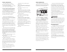
SPEAKER OUTPUTS
The e1200’s speaker outputs are designed to
accept 8 AWG - 16 AWG wire.
The e1200 is designed to deliver power into
speaker loads equal to or greater than 2Ω.
To connect the speaker wires to the amplifier,
first back out the set screws on the top of the
terminal block, using the supplied 2.5 mm hex
wrench. Strip 1/2 inch (12 mm) of insulation from
the end of each wire and insert the bare wire
into the terminal block, seating it firmly so that no
bare wire is exposed.While holding the wire in
place, tighten the set screw firmly, taking care not
to strip the head of the screw.
Speaker loads below 2Ω nominal are not
recommended and may cause the amplifier to
initiate a protection mode and shut itself off.
You will notice that there are two “+” positive
connections and two “–” negative connections.This
is to facilitate multiple speaker wiring.The two
positive and two negative connections are
connected in parallel inside the amplifier. Connecting
two speakers, each to one set of positive and
negative terminals, will result in a parallel speaker
connection. If only connecting one pair of speaker
wires, it is not necessary to use both sets of
connections.
IMPORTANT
!
IMPORTANT
!
8 JL AUDIO e1200