


SYSTEM CONFIGURATIONS
The e4300 is a flexible amplifier, well-suited for a
multitude of system configurations. In this section, the
most likely configurations are explained in detail.
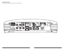
Once you have selected your desired
configuration, you can use the amplifier panel
drawing on pages 18 & 19 to mark the required
switch positions for easy reference.
BI-AMPLIFIED SYSTEMS
Bi-amplified systems are defined as systems in
which separate amplifier channels drive low-
frequency (LF)and high-frequency (HF) speakers and
are separately filtered to send appropriate frequency
ranges to each speaker system.
The most common application of bi-amplification
in mobile audio is to drive a subwoofer system from
one or more amplifiers or channels and component
speakers from separate amplifiers or channels.
The e4300 can be configured to drive a bi-
amplified system by itself or with a separate
subwoofer amplifier.
BI-AMPLIFIED SYSTEM WITH ONE e4300
In this configuration, channels 3&4 of the e4300
will drive subwoofers (stereo 75W x 2 at 2Ω or
bridged 150W x 1 at 4Ω) with low-pass filtering.
Channels 1&2 will drive component speakers in
stereo (75W x 2 at 2Ω) with high-pass filtering.
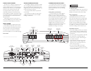
Input connection options for a bi-amplified system
with one e4300 are as follows:
A) No User Adjustability
Required:a basic source unit or processor with one
pair of stereo outputs.
Input Connections: a single pair of stereo source
unit outputs connected to the “CH 1 (Left)” and
“CH 2 (Right)” inputs of the e4300 (select “1&2”
on the “CH 3&4 Input From” switch.
Result: the relative level of the LF and HF
channels will be fixed by the e4300’s “Input Sens.”
settings and will not be user adjustable from the
front of the vehicle.
B) Fade Subwoofer Level vs. HFLevel
Required:a source unit or processor with two pairs
of stereo outputs.
Input Connections: the first stereo pair source unit
outputs is connected to the “CH 1 (Left)” and
“CH 2 (Right)” inputs of the e4300.The second
stereo pair of source unit outputs is connected to
the “CH 3 (Left)” and “CH 4 (Right)” inputs (select
“Discrete” on the “CH 3&4 Input From” switch).
Result: in this mode, the user has the ability to fade
or control the level of the LF channels relative to
the HF channels via the source unit’s fader control
without exceeding the maximum clean output level
set by each amplifier section’s “Input Sens.” controls.
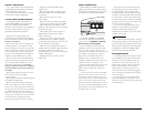
C) Subwoofer Level Control Only
Required:a source unit or processor with one pair
of stereo outputs and dedicated subwoofer outputs.
Input Connections: the main stereo pair of source
unit outputs is connected to the “CH 1 (Left)” and
“CH 2 (Right)” inputs of the e4300.The source
unit’s dedicated subwoofer output is connected to
the “CH 3 (Left)” and “CH 4 (Right)” inputs (select
“Discrete” on the “CH 3&4 Input From” switch).
Result: in this mode, the user has the ability to
control the absolute level of the LF channels relative
to the HF channels.
Set the “Input Sens.” in the “Channel 3 & 4
Controls” section with the source unit’s subwoofer
level control set at 3/4 of full output. See
Appendix A (page 14) for details.
Crossover Setup for Bi-Amplified System
with one e4300:
Once the input sections have been configured
appropriately,go to the “Channel 3 & 4 Controls”.
Select “LP” (low-pass) on the “Filter Mode” switch
and an appropriate “Filter Freq.” (100 Hz is a good
starting point).
Next, turn your attention to the “Channel 1 & 2
Controls” and select “HP” (high-pass) on the “Filter
Mode” switch and an appropriate “Filter Freq.”
(again, 100 Hz is a good starting point).
After proper adjustment of the “Input Sens.”
controls for both channel pairs using the method
shown in Appendix A (page 14), you can fine tune
filter frequencies and attenuate either pair of channels
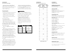
to achieve proper balance. For precise filter frequency
information refer to Appendix B (page 15).
IMPORTANT
!
JL AUDIO e4300 11
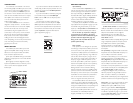
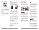
AMPLIFIER STATUS INDICATOR LIGHTS /
PROTECTION CIRCUITRY
There are two status indicator lights on the
input / control end of the amplifier:
1) “Power” (Green): lights to indicate that the
amplifier is turned on and operating normally.
2) “Protect” (Red): lights or flashes to indicate
that the amplifier protection circuitry has been
activated to prevent product failure.
a) If the red “Protect” indicator lights steadily
(without flashing), the amplifier has exceeded its safe
operating temperature.This causes the amplifier to
shut off in order to protect its circuitry. When the
amplifier’s temperature drops to a safe level, the red
“Protect” indicator will shut off and the amplifier
will return to normal operation.
b) If the red “Protect” indicator flashes
intermittently, the protection circuitry has detected a
short-circuit or a dangerously low impedance
connected to the amplifier output(s). Connecting
the speaker outputs to an impedance lower than
2Ω stereo (4Ω bridged) will cause this protection
mode to activate.The amplifier’s output may cycle
on and off when this protection mode is activated.
When the problem is eliminated, the amplifier will
return to normal operation.
SERVICING YOUR JL AUDIO AMPLIFIER
If your amplifier fails or malfunctions, please
return it to your authorized JL Audio dealer so
that it may be sent in to JL Audio for service.
There are no user serviceable parts or fuses
inside the amplifier.The unique nature of the
circuitry in the JL Audio amplifiers requires
specifically trained service personnel. Do not
attempt to service the amplifier yourself or
through unauthorized repair facilities.This will not
only void the warranty, but may result in the
creation of more problems within the amplifier.
If you have any questions about the installation or
setup of the amplifier not covered in
this manual, please contact your dealer or the
JL AUDIO Technical Department for assistance:
(954) 443-1100
9:00 AM – 5:30 PM Eastern Time,
Monday – Friday
10 JL AUDIO e4300