


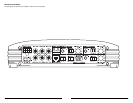


AMPLIFIER CONTROLS
Input Sensitivity
These controls, labeled “Input Sens.”,can be
used to match the source unit's output voltage(s)
to each input stage of the e6450 for maximum
clean output. Rotating an “Input Sens.” control
clockwise will result in higher sensitivity (louder for
a given input voltage). Rotating an “Input Sens.”
control counter-clockwise will result in lower
sensitivity (quieter for a given input voltage.)
To properly set the amplifier for maximum clean
output, please refer to Appendix A (page 12) in this
manual.After using this procedure, you can then
adjust any or all “Input Sens.” levels downward if this
is required to achieve the desired system balance.
Do not increase any “Input Sens.” setting for
any channel(s) of any amplifier in the system
beyond the maximum level established during the
procedure outlined in Appendix A (page 12).
Doing so will result in audible distortion and
possible speaker damage.
Filter Controls
Most speakers are not designed to reproduce
the full range of frequencies audible by the human
ear. For this reason, most speaker systems are
comprised of multiple speakers, each dedicated to
reproducing a specific frequency range. Filters are
used to select which frequency range is sent to
each section of a speaker system.The division of
frequency ranges to different speakers can be
done with passive filters (coils and/or capacitors
between the amplifier outputs and the speakers),
which are acceptable and commonly used for
filtering between mids and tweeters. Filtering
between subwoofer systems and satellite speaker
systems is best done with active filters, which cut
off frequency content at the input to the amplifier.
Active filters are more stable than passive filters
and do not introduce extraneous resistance,
which can degrade subwoofer performance.
The active filter built into each channel of the
e6450 can be used to eliminate potentially harmful
and/or undesired frequencies from making their way
through the amplifier sections to the speaker(s).This
serves to improve tonal balance and to avoid
distortion and possible speaker failure. Correct use
of these filters can substantially increase the
longevity and fidelity of your audio system.
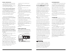
1) “Filter Mode” Control:The e6450 employs a
12dB per octave filter for each pair of channels (one
filter for channels 1&2, another filter for channels
3&4 and another filter for channels 5&6). Each of
these filters can be configured independently into
one of two filter types or defeated completely by
way of the three-position “Filter Mode” switches:
“Off”: Defeats the filter completely, allowing the full
range of frequencies present at the inputs to feed
the amplifier.This is useful for systems utilizing
outboard crossovers or requiring full-range
reproduction from one, two or all of the e6450’s
channel pairs.
“LP” (Low-Pass): Configures the filter to attenuate
frequencies above the selected filter frequency at a
rate of 12dB per octave.This is useful for
connection of subwoofer(s) to one, two or all of
the e6450’s channel pairs in a bi-amplified system.
“HP” (High-Pass): Configures the filter to attenuate
frequencies below the selected filter frequency at a
rate of 12dB per octave.This is useful for
connection of component speakers to one, two or
all of the e6450’s channel pairs in a bi-amplified
system.
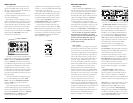
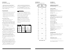
2) “Filter Freq.(Hz)”The filter frequency
markings surrounding this rotary control are for
reference purposes and are generally accurate to
within 1/3 octave or better. If you would like to
select the filter cutoff frequency with a higher level of
precision, consult the chart in Appendix B (page 13).
Tuning Hint: If you are using the e6450 to drive a
subwoofer system (“LP”mode), a component
satellite speaker system (“HP”mode) or both,
100 Hz is a good baseline “Filter Freq. (Hz)”
setting.After properly adjusting the “Input Sens.”,
as outlined in Appendix A (page 12), you can fine
tune the “Filter Freq. (Hz)” control to achieve the
desired system frequency response.
JL AUDIO e6450 7
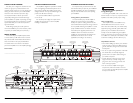
INPUT SECTION
The e6450’s input section allows you to send
signal to the amplifier section through the use of
two, four or six inputs and offers two distinct input
connection options.These are:
1)Three pairs of traditional RCA type
connections designed to accept input from source
units with line level outputs.
2) An eight-pin connector designed to accept
input from amplified sources such as factory source
units or source units not equipped with line level
outputs. Channels 5 & 6 of the e6450 do not have
discrete inputs on this connector. However, signal
from channels 1 & 2 and channels 3 & 4 can be
summed and sent to channels 5 & 6 when “SUM” is
selected with the “Input Mode” switch in the
Channel 5 & 6 Controls section.
If you wish to send six discrete channels into the
e6450, simply use all six inputs and set the “Input
Mode” switch in the “Channel 5 & 6 Controls”
section to “Discrete”.This will most commonly be
accomplished by using the six RCA type connections
(it is possible to use the eight-pin connector with
amplified signals for input into channels 1, 2,3 & 4
and RCA type connections for input into channels 5
& 6, however, most source units with a dedicated
subwoofer output will also have at least one pair of
full range outputs).
If you wish to feed all six channels by using only
four channels of full-range input, set the “Input
Mode” switch in the “Channel 5 & 6 Controls”
section to “SUM” and use only the inputs to
channels 1, 2, 3 & 4.
If you wish to feed all six channels by using two
channels of full-range input and two channels of low-
frequency input (subwoofer output from the source
unit), set the “Input Mode” switch in the “Channel 5
& 6 Controls” section to “Discrete”. It will be
necessary to split the full-range signals with
y-adaptors and feed these signals into the inputs to
channels 1, 2, 3 & 4.The dedicated subwoofer signal
should be sent to channels 5 & 6.
If you wish to use only two channels of input to
deliver signal to all six amplifier channels, it will be
necessary to split the two signals with y-adaptors
and feed these signals into the inputs to channels
1, 2, 3 & 4.Set the “Input Mode” switch in the
“Channel 5 & 6 Controls” section to “SUM” and
use only the inputs to channels 1, 2, 3 & 4.
The same input connection option does not
need to be used for each channel pair.The “Input
Sens.” adjustment is independent for each channel
pair and must be adjusted based on input level and
the impedance of the load on that pair of channels.
Specific “Input Sens.” adjustment information is
given in Appendix A (page 12).
6 JL AUDIO e6450