


8 | JL Audio - HD600/4 Owner’s Manual
9
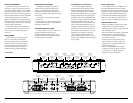
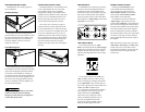
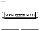
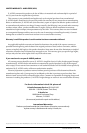
AMPLIFIER INPUTS
The HD600/4 has two separate input sections,
one for the “Front” left and right channels and
another for the “Rear” left and right channels.
Each section consists of a pair of RCA-type input
jacks on the Connection Panel of the amplifier
and a pair of input controls on the Control Panel
of the amplifier: an “Input Voltage” switch and an
“Input Sens.” rotary control.
Rear Preouts
Remote
Level
Control
Front
Inputs
L
R
L
R
+12 VDC Ground Remote
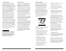
“INPUT MODE” SWITCH
The Control Panel houses an “Input
Mode” switch located under the “General Setup”
heading. This switch allows operation of all four
amplifier channels with only one pair of input
signals or with independent front and rear input
signal pairs.
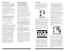
To use separate inputs for the “Front” and
“Rear” amplifier sections, (in order to permit
front-to-rear fading, for example), select “4 Ch.”
on the “Input Mode” switch. In this mode, you
must connect separate pairs of input cables to the
“Front” and “Rear” amplifier inputs.
To operate all four channels of the HD600/4
with a single pair of stereo inputs, select the
“2 Ch.” position on the “Input Mode”
switch and connect a single pair of input
cables to the “Front” input jacks only. In
this mode, the amplifier will route the
signals connected to the “Front” inputs to
the Front and Rear amplifier channels.
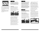
CHANNEL CONTROL SECTIONS
Flanking the “General Setup” section
on the Control Panel of the amplifer are
two sets of identical controls: one for the
“Rear Channel Controls” (on the left side)
and one for the “Front Channel Controls”
of the amplifier (on the right side).
In each of these sections you will find an
“Input Voltage” range switch and a rotary
control labeled “Input Sens.” (Input Sensitivity).
These controls are designed to match the input
sensitivity of the HD600/4 to the specific signal
source that is feeding it and must be adjusted,
with care, following the procedures outlined in
this manual. Failure to make correct adjustments
can result in weak output, excessive distortion
and/or undesirable noise in the audio output of
the amplifier!
Note: The Channel Control sections also house
“Filter Mode”, “Filter Slope” and “Filter Freq.”
controls. These are crossover filter controls
and will be discussed in the next section of this
manual. This section will explain the Input
Controls only.
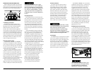
AMPLIFIER MOUNTING OPTIONS
The HD600/4 has two mounting options to
ease in installation.
Standard Mounting
The standard method of mounting requires
removal of the four corner caps with the 3/16-inch
hex wrench included with your amplifier. Using
appropriate mounting screws (not included),
secure the amplifier in all four corners and
replace the corner caps.
Lateral Mounting Feet
Lateral Mounting Feet are also included with
your HD600/4 to provide an alternative mounting
option. Each mounting foot should be attached
to the bottom of the amplifier by screwing the
provided bolt into the bottom of the amplifier and
up into the corner cap with the supplied 1/8-inch
hex wrench. Next, using appropriate mounting
screws (not included), secure the amplifier by its
four Lateral Mounting Feet.
Check before drilling any holes in your vehicle
to make sure that you will not be drilling
through a gas tank, brake line, wiring harness
or other vital vehicle system.
CONTROL PANEL SECURITY COVER
The HD600/4 features a Control Panel Security
Cover. When installed, the cover ensures that
your amplifier settings are not accidentally
changed while creating a clean aesthetic for the
amplifier and your installation. The control panel
security cover is pre-installed at the factory and
must be temporarily removed for access to the
controls described throughout this manual.
The security cover is secured by a single 2.5
mm hex-head screw at the far right of the panel.
Loosen the hex-head screw to release the security
cover (it is not necessary to completely remove the
screw). To re-install the security cover once all
adjustments have been made, insert the tongue on
the cover’s left edge into the groove where the left-
side heatsink meets the control panel, hinge the
panel closed and secure the screw using the
supplied 2.5 mm hex wrench. Do not overtighten
the screw.