


8 JL Audio
9
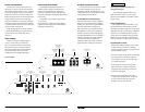
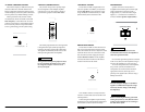
“BASS BOOST” CONTROL
The J2-1000.1 includes a single band, boost-
only bass equalizer controlled by a rotary knob
marked “Bass Boost”. This control has a boost
range of 0dB (full-counterclockwise) to +12dB
(full-clockwise) and is centered at 45 Hz.
LP Filter Frequency (Hz)
Input Sens.
Bass Boost Remote Level Port
min max 40 300 O +12dB
ProtectPower
High-Level Inputs
LEFT
RIGHT
LEFT
RIGHT
Amplifier ControlsAmplifier Inputs Pre-Outs Amplifier Status
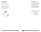
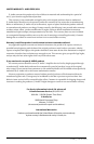
REMOTE LEVEL CONTROL
The J2-1000.1 includes a remote level control
that can be mounted in the front of the vehicle.
This control allows the owner to adjust the overall
subwoofer level to taste. To connect the remote
bass control knob, insert its plug into the jack
labeled “Remote Level Port” on the amplifier
and route the cable and control to the desired
location in the front of the vehicle.
LP Filter Frequency (Hz)
Input Sens.
Bass Boost Remote Level Port
min max 40 300 O +12dB
ProtectPower
High-Level Inputs
LEFT
RIGHT
LEFT
RIGHT
Amplifier ControlsAmplifier Inputs Pre-Outs Amplifier Status
Care should be taken to securely mount this
control in a manner that does not interfere with
vehicle operation.
When setting the amplifier’s input sensitivity,
the Remote Level Control should be unplugged or
at full clockwise rotation (maximum level).
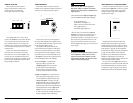
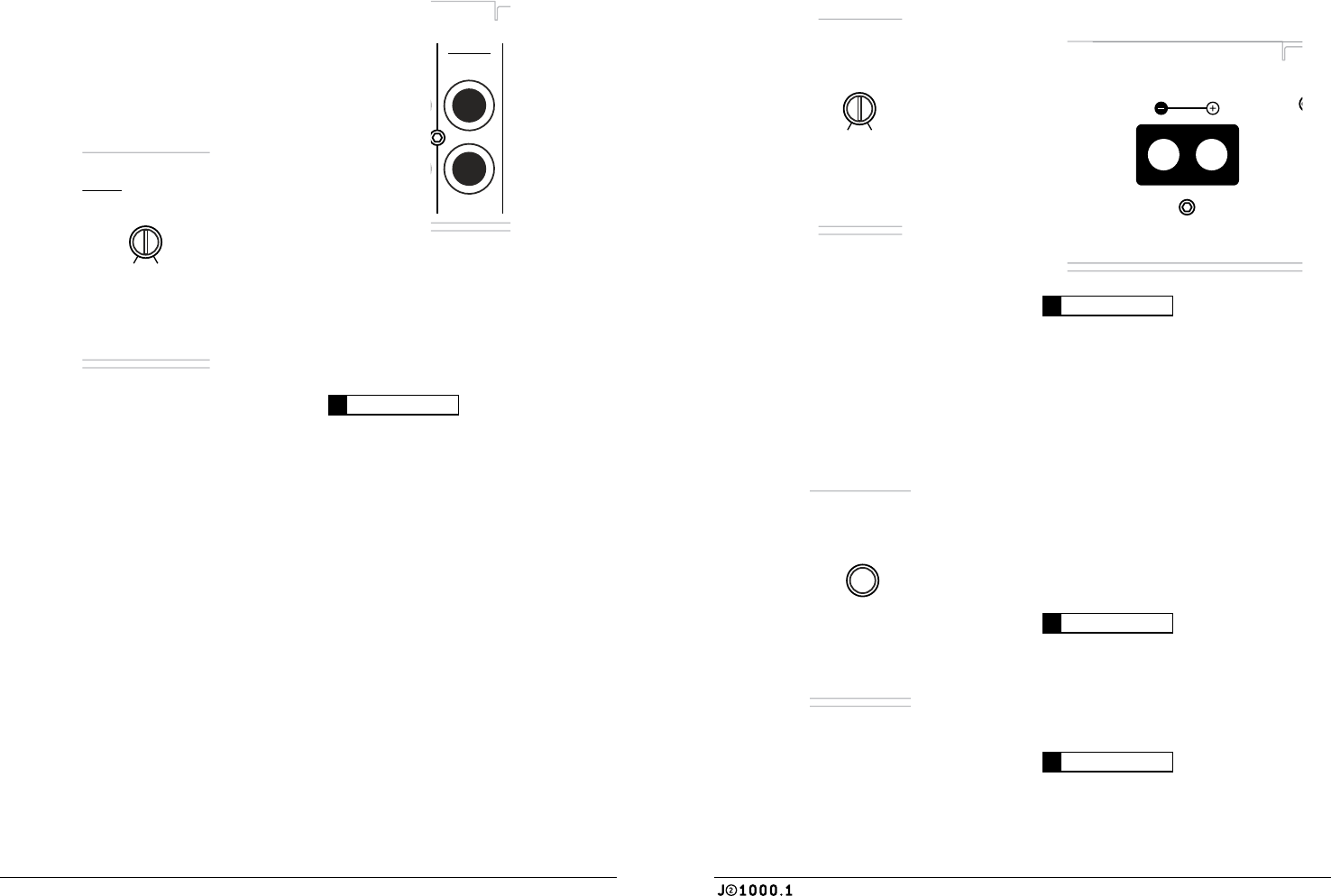
SPEAKER OUTPUT
Speaker connection to the J2-1000.1 is
straightforward and takes place at the far right
of the power/speaker connection panel. A
single positive (“+”) connection and a single
negative (“–”) connection are available via a
connector labeled “Speaker Output (Mono)”.
Made in China
35A35A35A
IMPORTANT
!
Speaker loads below 1Ω nominal are not
recommended and will cause the amplifier to
enter into a protection mode.
Do not chassis ground any speakers connected
to this or any other JL Audio amplifier. Doing so
will cause the amplifier to go into protection.
To connect the speaker wires to the amplifier,
strip 1/2-inch (12 mm) of insulation from
each speaker wire and insert them into their
appropriate connector (observing correct
polarity). Then, tighten each connector using a
Phillips screwdriver.
IMPORTANT
!
Do NOT attempt to “bridge” two J2-1000.1’s
together or combine their output to a single
load in any manner. Doing so will damage
the amplifier(s).
IMPORTANT
!
Before reconnecting the battery ground and
turning the system on, verify that all control
settings on the amplifier are set according to
the needs of the system.
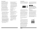
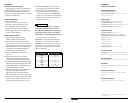
“LP FILTER” CROSSOVER CONTROL
The J2-1000.1 employs a 12dB/octave low-pass
(LP) active filter for its internal channel. This
feature is designed to attenuate frequencies above
its filter frequency, so that the system’s subwoofers
do not reproduce any audible midrange content.
The low-pass filter in the J2-1000.1 is fully
variable between 40 Hz and 300 Hz via the “LP
Filter Frequency” control knob. The 12 o’clock
position corresponds to a 150 Hz filter frequency.
The “10 o’clock” position corresponds to 80 Hz
and is a good starting point for system tuning.
LP Filter Frequency (Hz)
Input Sens.
Bass Boost Remote Level Port
min max 40 300 O +12dB
ProtectPower
High-Level Inputs
LEFT
RIGHT
LEFT
RIGHT
Amplifier ControlsAmplifier Inputs Pre-Outs Amplifier Status
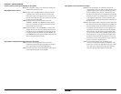
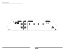
“PREOUTS” (PREAMP OUTPUTS)
The J2-1000.1 incorporates a preamp output
section, designed to make multiple amplifier
systems easy to set up. This section consists of
a pair of RCA-type jacks marked “Pre-Outs”.
LP Filter Frequency (Hz)
Input Sens.
Bass Boost Remote Level Port
min max 40 300 O +12dB
ProtectPower
High-Level Inputs
LEFT
RIGHT
LEFT
RIGHT
Amplifier ControlsAmplifier Inputs Pre-Outs Amplifier Status
The Preamp outputs deliver the same signal that
is being fed to the inputs. (If the input signal are
full-range, the preamp outputs will be full-range).
This signal is not affected by the bass boost or LP
FIlter processing selected for the amplifier.
IMPORTANT
!
The signal level of the preamp output is always
low level regardless of whether you are using
the “High-Level Inputs” or the Low-Level
(RCA-jack) Inputs.