


➔➔
➔➔➔
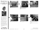
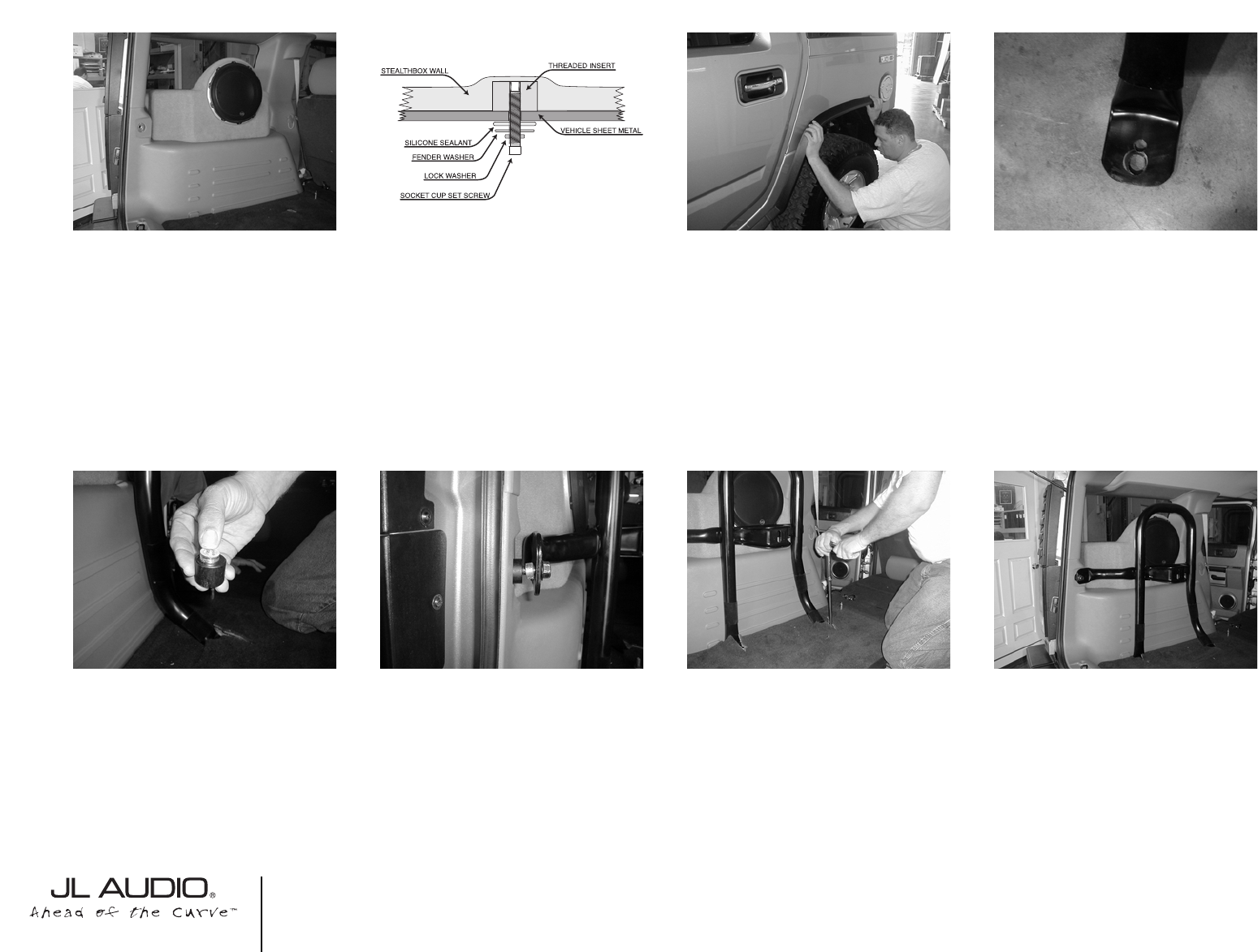
STEP 15: Back out the socket cup set screws, that
was threaded in from STEP 11, to expose 1-1/4”.
Connect the speaker wire to the terminal and place
the enclosure into position.
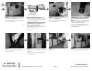
STEP 19: With the spare tire rack placed into
position. Loosely tighten the lower factory bolts to
the lower mounting feet.
Cont.
From
Previous
Page
Continued on Next Page ➔
➔
STEP 16: (Outside the vehicle) Place the sup-
plied hardware in order onto the exposed socket
cup screw. If more exposed threads are needed, back
out the socket cup set screws.
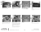
*Do not back out too much, you can cause a
conflict when mounting the plastic inner
wheel well, back into location.*
Fender washer, flat washer, lock washer and hex nut
onto each socket cup set screw.
Secure tightly.
STEP 20: Placed A supplied spacer, between each
upper mounting foot of the spare tire rack and the
side panel.
Loosely secure each upper mount assembly with a
supplied hex cap screw.
➔
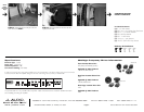
STEP 21: Align the spare tire rack, for proper
positioning.
STEP 22: With the spare tire rack properly posi-
tioned, it should not interfere with the enclosure.
STEP 17: Mount the plastic inner wheel well and
plastic trim from STEPS 6 & 7.
You didn’t leave too much of the socket cup set
screws exposed, did you?
*STEPS 18-24 are for only for the vehicles
that are equip with the internal spare tire.*
STEP 18: The spare tire rack needs to be modi-
fied for the proper spacing,This needs to be accom-
plished on both bottom mounting feet.
Measure 9/16” from the center of the factory
mounting hole, back. Mark and drill with the a 1/2”
drill bit or Uni-bit®.
SB-GM-HUMR2/12W6v2, JL AUDIO, Inc 2004
Sheet SKU#011182 Revision8/5/2004
Page 3
www.jlaudio.com