


Continued on Next Page
SB-POL-RNGR/SYS INSTR_SKU# 011278
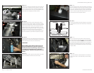
S T E P 5
Set the Square U-Bolt in place over the bottom cross-dash
bar, slide it towards the drivers side of the vehicle.
D E T A I L
Enlarge the hole in the cross-dash channel by drilling from
below (there is no access from above) again, ensure that you
will be enlarging the correct hole in the channel!
*CAUTION*
Before drilling, always make sure that you are not
going to be drilling into any gas lines, brake lines,
transmission lines, electrical wiring, exhaust systems
or anything else that might cause a reduction in
your weekly pay. Always wear eye protection when
drilling.
D E T A I L
This DETAIL at left, shows a view looking down into the
cross-dash channel, note the relation of the Relay holding
screw and the enlarged hole. Make sure that the threaded
insert lines up with the correct hole so that you will only
need to drill one hole. There will be a 3/8-16x 1 1/2” Hex
Head Bolt, Split Lock Washer and, 3/8x 1 1/4”Fender Washer
inserted into this channel and, through the hole then
through the 1/2” Aluminum Spacer and threaded into the
top of the Stealthbox® (see DETAIL illustration at far right).
S T E P 4
Looking from under the hood take note of the location of
the relay that is screwed to the cross channel. inside that
channel on the bottom there is a hole that should line up
with the threaded insert in the top of the Stealthbox®, this
hole needs to be enlarged (see DETAILS below)
Page 2 • JL Audio, Inc 2008
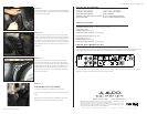
S T E P 7
Sliding the enclosure back into place, make sure that the
wire is not pinched or damaged and align the top threaded
insert with the hole enlarged in STEP 4. Start the hardware
as mentioned before into the threaded insert. Also align the
Custom Aluminum Bracket and the Square U-Bolt and start
a Flat Washer, Split Lock Washer and Hex Nut on each leg of
the Square U-Bolt.
D E TA I l
This is how the hardware should be arranged in the channel
then, threaded into the top of the enclosure. (as mentioned
at far left)
S T E P 8
Once all of the hardware is started, tighten all of the fasten-
ers, rotating from each nut to another like you were chang-
ing a tire.
S T E P 6
Install the included Custom Aluminum Bracket on the drivers
side of the subwoofer enclosure as shown using the supplied
3/8-16x 1” Hex Head Bolt, Split Lock Washer and Flat Washer,
these fasteners should be snug but, do not need to be tight
at this time. Install a length of wire that will reach from the
mounted enclosure to the amplifier location.
THREADED INSERT
1/2”ALUMINUM SPACER
LOCK WASHER
FLAT WASHER
STEALTHBOX WALL
HEX BOLT
CROSS-DASH CHANNEL
Relay Screw
Enlarged Hole