


3
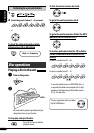
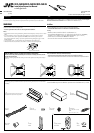
Typical connections / °“√‡™◊ËÕ¡μËÕ·∫∫ª°μ
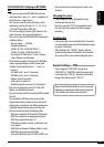
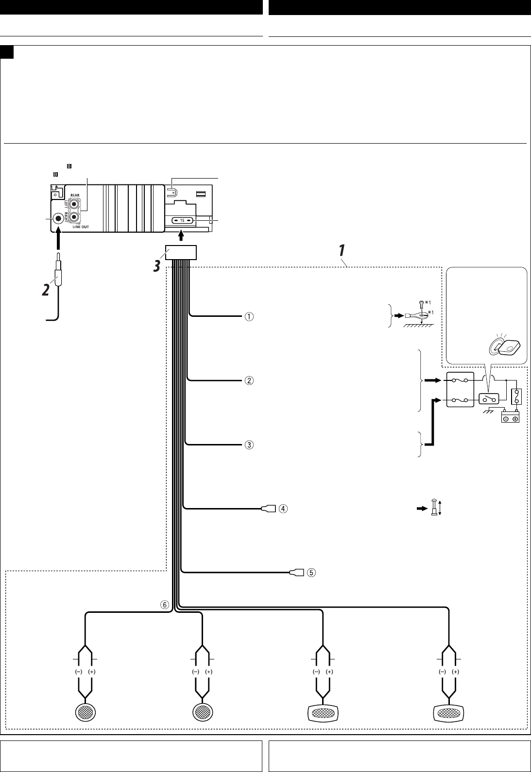
Before connecting: Check the wiring in the vehicle carefully. Incorrect connection may cause serious
damage to this unit.
The leads of the power cord and those of the connector from the car body may be different in color.
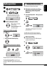
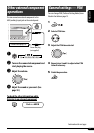
1 Connect the colored leads of the power cord in the order specified in the illustration below.
2 Connect the antenna cord.
3 Finally connect the wiring harness to the unit.
Purple
’¡Ë«ß
Purple with black stripe
’¡Ë«ß·∂∫¥”
Green
’‡¢’¬«
Green with black stripe
’‡¢’¬«·∂∫¥”
Gray
’‡∑“
Gray with black stripe
’‡∑“·∂∫¥”
White
’¢“«
White with black stripe
’¢“«·∂∫¥”
ENGLISH
‰∑¬
°ËÕ•∑”°“•‡™•ËÕ¡μËÕ: μ•«®†Õ•°“•‡¥‘•†“¬‰ø„•••¬•μÏլ˓ߕ–¡—¥•–«—լ˓„ÀȺ‘¥æ•“¥„•°“•‡™•ËÕ¡μËÕ™ÿ¥ª•–°Õ•™ÿ¥•’
°“•‡™•ËÕ¡μËÕº‘¥æ•“¥Õ“®∑”„Àȇ°‘¥§«“¡‡†’¬À“¬•È“¬·•ß°—•™ÿ¥ª•–
°Õ••’ȉ¥È“•μ–°—Ë«¢Õ߆“¬‰ø ·•–¢ÕßÕÿª°••ÏμËÕ‡™•ËÕ¡®“°μ—«• ß••Õ“®¡’’ ∑’ˉ¡Ë‡À¡•Õ•°—
1 μËÕ“¬‰ø’μ“¡≈”¥—∫∑’Ë√–∫ÿ„π√Ÿª¥È“π≈Ë“ß
2 ‡™◊ËÕ¡μËÕ°—∫“¬Õ“°“»
3 ÿ¥∑È“¬ μËÕË«π§«∫§ÿ¡°“√‡¥‘𓬉ø‡¢È“°—∫™ÿ¥ª√–°Õ∫™ÿ¥π’È
A
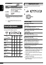
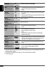
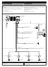
ELECTRICAL CONNECTIONS
°“√‡™◊ËÕ¡‚¥¬„™È ‰øøÈ“
To the automatic antenna if any (250 mA max.)
‡“Õ“°“»‰øøÈ“Õ—μ‚π¡—μ‘ À“°¡’ (¢π“¥Ÿß¸¥ 250 mA)
To the remote lead of other equipment (200 mA max.) — only for KD-G396/KD-G395
μËÕ‡¢È“°—∫Õª°√≥ÏÕË◊π (¢π“¥Ÿß¸¥ 200 mA) — ”À√—∫ KD-G396 À√◊Õ KD-G395 ‡∑Ë“π—Èπ
To the metallic body or chassis of the car
μËÕ°—∫‚§√ß‚≈À–À√◊Õ‡™´‘¢Õß√∂¬πμá
To a live terminal in the fuse block connecting to the car battery
(bypassing the ignition switch) (constant 12 V)
μËÕ°—∫¢—È«∑’Ë¡’°√–·‰øøÈ“„π·ºßø‘«Ï ´÷ËßμËÕ°—∫·∫μ‡μÕ√’Ë√∂¬πμ
( ‚¥¬‰¡ËμÈÕß„™È«‘∑™Ï®ÿ¥√–‡∫‘¥) (12 ‚«≈∑ϧß∑’Ë)
To an accessory terminal in the fuse block
μËÕ°—∫¢—È«Ë«πª√–°Õ∫„π·ºßøî«
Right speaker (rear)
≈”‚æߢ«“ (À≈—ß)
Left speaker (rear)
≈”‚æß´È“¬ (À≈—ß)
Right speaker (front)
≈”‚æߢ«“ (ÀπÈ“)
Left speaker (front)
≈”‚æß´È“¬ (ÀπÈ“)
*
1
‰¡Ë‰¥È„ÀÈ¡“°—∫™ÿ¥ª√–°Õ∫π’È
*
2
°ËÕπ°“√μ√«®Õ∫°“√∑”ß“π¢Õß™ÿ¥ª√–°Õ∫π’È°ËÕπ∑’Ë®–μ‘¥μ—Èß μÈÕßμËÕ“¬μ–°—Ë«π’È°ËÕπ
¡‘©–π—Èπ®–‰¡“¡“√∂‡ª‘¥‡§√◊ËÕ߉¥
15 A fuse
øî«Ï¢π“¥ 15 A
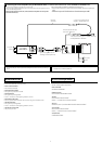
Line out (see diagram
) — only for KD-G396/KD-G395
“¬ÕÕ° (¥Ÿ·ºπ¿Ÿ¡ ) — ”À√—∫ KD-G396 À√◊Õ KD-G395 ‡∑Ë“π—Èπ
Antenna terminal
¢—È«“¬Õ“°“»
Rear ground terminal
®ÿ¥‡™◊ËÕ¡μËÕ “¬¥‘π¥È“πÀ≈—ß
*
1
Not supplied for this unit.
*
2
Before checking the operation of this unit prior to installation, this lead must be connected, otherwise the power
cannot be turned on.
Ignition switch
«‘∑™Ï®ÿ¥√–‡∫‘¥
Fuse block
·ºßøî«
Black
’¥”
Blue with white stripe
’πÈ”‡ß‘π≈“¬¢“«
Red
’·¥ß
Yellow *
2
’‡À≈◊Õß *
2
Blue
»’øÈ“
Install3-4_KD-G396_009A_TH.indd 3 8/22/07 2:23:40 PM