


3
SPECIFICATIONS
KS-AX3104 KS-AX3102 KS-AX3101D
Power Output
• Normal Mode:
Signal-to-Noise Ratio
60 W RMS × 4 channels at 4 Ω and ≤ 1% THD + N
76 dBA (reference: 1 W into 4 Ω)
65 W RMS × 2 channels at 4 Ω and ≤ 1% THD + N
76 dBA (reference: 1 W into 4 Ω)
250 W RMS × 1 channels at 4 Ω and ≤ 1% THD + N
60 dBA (reference: 1 W into 4 Ω)
Power Output
• Normal Mode:
90 W RMS × 4 channels at 2 Ω and ≤ 1% THD + N 90 W RMS × 2 channels at 2 Ω and ≤ 1% THD + N 400 W RMS × 1 channels at 2 Ω and ≤ 1% THD + N
• Bridge Mode:
150 W RMS × 2 channels at 4 Ω and ≤ 1% THD + N 150 W RMS × 1 channels at 4 Ω and ≤ 1% THD + N
—
Maximum Power Output 800 W (400 W × 2) 400 W 800 W
Load Impedance
• Normal Mode:
4 Ω (2 Ω to 8 Ω allowance) 4 Ω (2 Ω to 8 Ω allowance) 4 Ω (2 Ω to 8 Ω allowance)
• Bridge Mode:
4 Ω (4 Ω to 8 Ω allowance) 4 Ω (4 Ω to 8 Ω allowance)
—
Frequency Response 5 Hz to 50,000 Hz ( +0 dB, –3 dB) 5 Hz to 50,000 Hz ( +0 dB, –3 dB) 20 Hz to 200 Hz ( +0 dB, –3 dB)
Input Sensitivity/Impedance
2 V/21 kΩ (0.3 V to 6 V, variable) 2 V/21 kΩ (0.3 V to 6 V, variable) 2 V/40 kΩ (0.3 V to 6 V, variable)
Distortion Less than 0.04% (at 1 kHz) Less than 0.04% (at 1 kHz) Less than 0.08% (at 100 Hz)
Power Requirement DC 14.4 V (11 V to 16 V allowance) DC 14.4 V (11 V to 16 V allowance) DC 14.4 V (11 V to 16 V allowance)
Grounding system Negative ground Negative ground Negative ground
Dimensions (W×H×D) 335 mm × 51 mm × 212 mm
(13-
4
/16 in. × 2-
1
/16 in. × 8-
6
/16 in.)
202 mm × 51 mm × 212 mm
(8 in. × 2-
1
/16 in. × 8-
6
/16 in.)
222 mm × 51 mm × 212 mm
(8-
12
/16 in. × 2-
1
/16 in. × 8-
6
/16 in.)
Mass (approx.) 2.43 kg (5.3 lbs) 1.52 kg (3.4 lbs) 1.83 kg (4.0 lbs)
Accessories Speaker input connector 3P × 2
Mounting Screw
φ
4 × 20 mm (13/16 in.) × 4
Speaker input connector 3P × 1
Mounting Screw
φ
4 × 20 mm (13/16 in.) × 4
Speaker input connector 3P × 1
Mounting Screw
φ
4 × 20 mm (13/16 in.) × 4
Design and specifi cations are subject to change without notice.
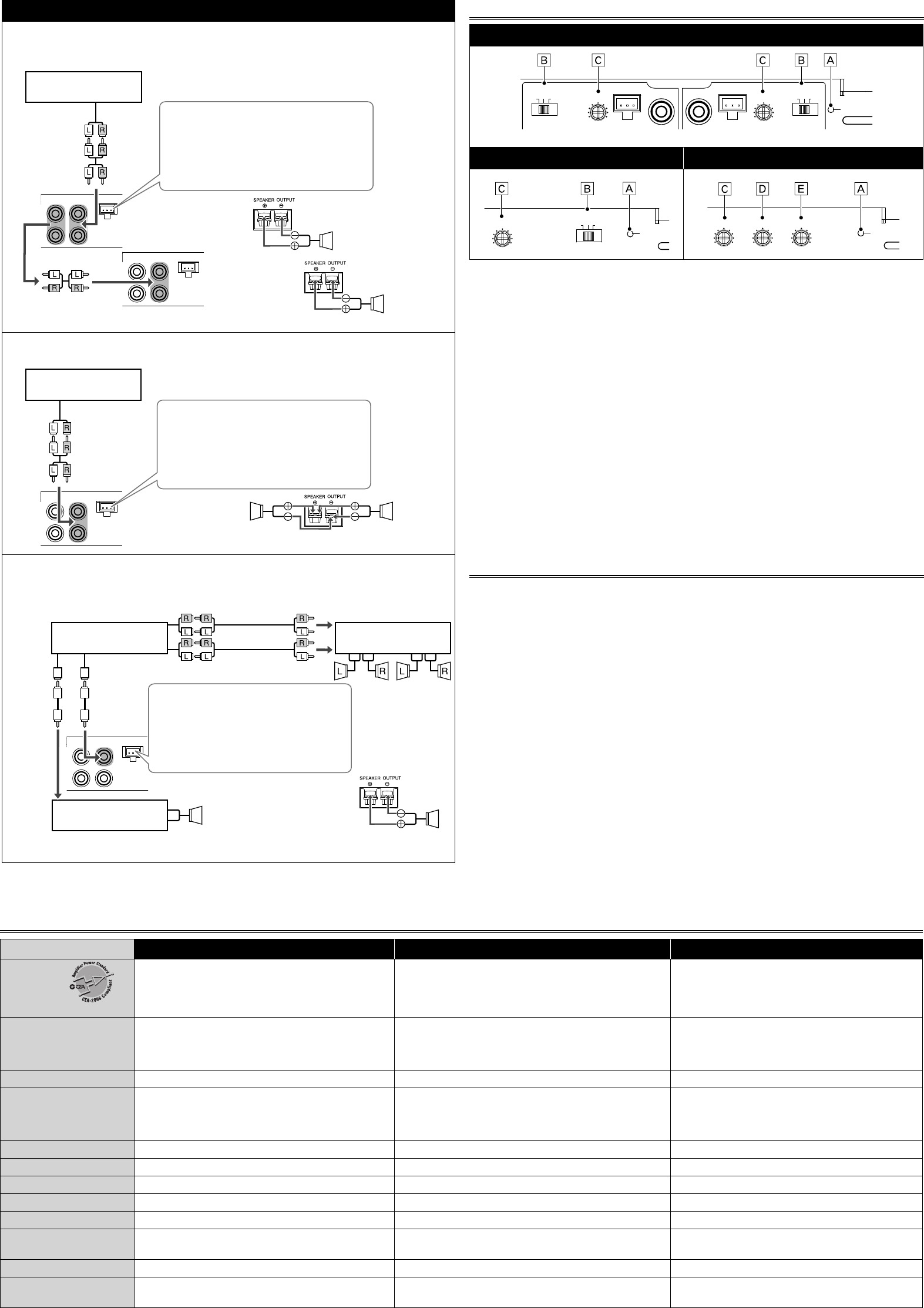
CONTROLS
KS-AX3104
CROSSOVER
OFF
LPF
HPF
OFF
LPF
HPF
CROSSOVER
POWER
HIGH INPUT
L/
MONO L/MONO
HIGH INPUT
MIN MAX
LEVEL
MIN MAX
LEVEL
INPUT
FRONT REAR
KS-AX3102 KS-AX3101D
OFF
LPF
HPF
CROSSOVER
POWER
MIN MAX
LEVEL
MIN MAX
LEVEL
MIN MAX
BASS BOOST
50Hz 200Hz
LPF
POWER
Å POWER indicator
The green lamp lights while the unit is turned on.
ı CROSSOVER filter switch
OFF: Normally set to this position. The switch is preset to this position when the unit is
shipped.
LPF: Set to this position when you want to turn on the LPF (Low-Pass Filter) switch. The Low-
Pass Filter transmits frequencies lower than 80 Hz.
HPF: Set to this position when you want to turn on the HPF (High-Pass Filter) switch. The
High-Pass Filter transmits frequencies higher than 150 Hz.
Ç Input LEVEL controller
The input level can be adjusted with this control when this unit is connected to other source
equipment. Adjust the level while listening to the sound. This control is preset to MIN when
the unit is shipped.
Î BASS BOOST controller
Turning this boosts the 45 Hz frequency within the range of 0 dB to +18 dB. Adjust the level
while listening to the sound. This controller is preset to MIN when the unit is shipped.
‰ LPF (Low-Pass Filter) controller
Adjust the cutoff frequency (the Low-Pass Filter transmits frequencies lower than the cutoff
frequency) within the range of 50 Hz to 200 Hz. Adjust the level while listening to the
sound. This controller is preset to 50 Hz when the unit is shipped.
TROUBLESHOOTING
The POWER indicator does not light.
• Change the fuses if the current one is blown.
• Connect the ground lead securely to a metal part of the car.
• Turn on the equipment connected to this unit.
• Confirm the battery voltage (11 V to 16 V).
• Use a relay if your system employs too many amplifiers.
• Leave the unit turned off to cool it down if it heats up abnormally.
No sound is heard.
• Confirm the connections for the power supply (see "POWER SUPPLY" on page 1).
• Connect the RCA pin cords to the INPUT jacks, or the speaker input connector to the HIGH
INPUT terminal.
• Confirm the speaker wirings and the position of the CROSSOVER filter switch (See “SPEAKER
CONNECTIONS” on page 2).
Alternator noise is heard.
• Keep the leads of the POWER terminals away from the RCA pin cords.
• Keep the RCA pin cords away from other electrical cables in the car.
• Connect the ground lead securely to a metal part of the car.
• Make sure the speaker negative leads do not touch the car chassis.
• Connect a bypass capacitor across the accessory switches (horn, fan, etc....).
Noise is made when you connect the unit to an AM (MW/LW) tuner.
• Move all the leads of this unit away from the antenna (aerial) lead.
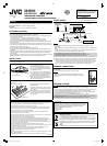
KS-AX3101D
2-Subwoofer system (2 amplifi ers)
• Use the speakers with an impedance of 2 Ω to 8 Ω.
• Incoming signals from INPUT jacks are emitted through the PRE OUT jacks.
HIGH INPUT
INPUT
R
L/
MONO
PRE OUT
R
L
HIGH INPUT
INPUT
R
L/
MONO
PRE OUT
R
L
Line out (Rear)
or
Subwoofer out
JVC car receiver, etc.
ı Speaker input connector.
Connector lead To Receiver
a White "LEFT (+)"
=
Left (+) lead
b Black "RECEIVER GND"
=
Chassis*
1
c Gray "RIGHT (+)"
=
Right (+) lead
Å
Subwoofer
*
2
Subwoofer
*
2
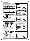
2-Subwoofer system
• Use the speakers with an impedance of 4 Ω to 8 Ω.
HIGH INPUT
INPUT
R
L/
MONO
PRE OUT
R
L
Line out (Rear)
or
Subwoofer out
*
2
JVC car receiver, etc.
ı Speaker input connector.
Connector lead To Receiver
a White "LEFT (+)"
=
Left (+) lead
b Black "RECEIVER GND"
=
Chassis*
1
c Gray "RIGHT (+)"
=
Right (+) lead
Å
Subwoofer
Subwoofer
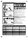
5-speaker system plus subwoofer—5.1-channel (3 amplifi ers)
• Use the speakers with an impedance of 2 Ω to 8 Ω.
• Be sure to connect the line output from the receiver to the left (L) jack on this unit.
HIGH INPUT
INPUT
R
L/
MONO
PRE OUT
R
L
JVC car receiver, etc.
ı Speaker input connector.
Connector lead To Receiver
a White "LEFT (+)"
=
Left (+) lead
b Black "RECEIVER GND"
=
Chassis*
1
c Gray "RIGHT (+)"
=
Left (+) lead
Å
Subwoofer
*
2
JVC amplifier, etc.
(Purchased separately)
JVC amplifier, etc.
(Purchased separately)
Center Speaker
Front
Speaker
Rear
Speaker
Line out (Front)
Line out (Rear)
*
2
*
2
*
2
Line out
(Center)
Subwoofer out
KSAX310_EN_GE_NL_FR_UK_AR.indd 3KSAX310_EN_GE_NL_FR_UK_AR.indd 3 11/4/10 11:10:59 AM11/4/10 11:10:59 AM