


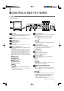
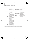


6
24
22
23
25
OUT
IN
OUTIN
Y/C
AFC
NORMAL
FAST
OUTIN
SET UP
CUT OFF
B
1
R
G
DRIVE
R
G
VIDEO A
OUTIN
EXT SYNC
AUDIO
TALLY/
REMOTE
OUTIN
VIDEO B
AC IN
DC IN
12V
A
B
2
1
2
+
-
< Rear Panel >
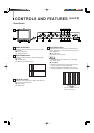
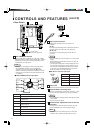
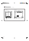
CONTROLS AND FEATURES
(cont'd)
OUTIN
AFC
NORMAL
FAST
TALLY/
REMOTE
A
B
21
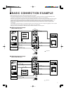
To AC outlet
(120 V AC, 50/60 Hz)
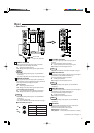
21 TALLY/REMOTE terminal
External control terminal (DIN 8-pin). Tally lamp, VIDEO
A/B (input selection), Under Scan, External Sync, 4:3/16:9
(aspect ratio), Pulse Cross, and Color Off modes can be
controlled from an external unit.
Note:
* When you’re controlling the monitor externally via the
TALLY/REMOTE terminal, set all corresponding
switches on the front panel to the OFF (—) position.
(Whichever switch is pressed first has priority so remote
switches may not function if the panel switches are ON
(_) position.)
Ⅵ TALLY/REMOTE terminal pin layout
Pin No. Signal
1 TALLY lamp ON/OFF
2 Input Select A/B
(VIDEO A/B)
3 UNDER SCAN ON/OFF
4 EXT SYNC ON/OFF
(External Sync)
5 ASPECT RATIO 4 : 3 /16 : 9
(4 : 3 /16 : 9)
6 PULSE CROSS ON/OFF
7 COLOR OFF ON/OFF
8 GND
22 Power input connector
Supply power to either the AC IN or DC IN 12 V
connector.
[AC IN]
Connect the provided AC power cord between the AC IN
connector and an AC outlet (120 V AC, 50/60 Hz).
[DC IN 12 V]
Connect the 12 V DC power plug to the DC IN 12 V
connector.
Notes:
* See your dealer for more information on 12 V DC power
supply.
* When both AC IN and DC IN connectors are used, the
AC input has priority.
* The DC power supply does not automatically take over
if an AC outlet is unplugged or the AC power is cut off
when both AC and DC power supplies are connected.
In this case, press the POWER switch to set to OFF,
then press it again to turn the power ON.
Ⅵ DC IN 12 V connector pin layout
23 Power cord
Connect the provided power cord to the AC IN connector.
24 External battery mounting holes
Attach an external battery to either pair of holes (1 or 2) to
use 12 V DC power (depending on the type of battery).
Notes:
* External batteries manufactured by Anton Bauer or PAG
are available.
* See your dealer for details.
25 Switch/control adjustment holes for service
personnel
For adjustment of SET UP switch, CUT OFF (B, R, G)
control and DRIVE (R, G) control during servicing.
Note:
* These controls are exclusively for the use of service
personnel. Do not attempt to adjust them yourself.
DC IN
12V
1
3
2
4
Pin No. Signal
1 GND
2—
3—
4 12 V DC
1
2
3
4
5
6
7
8
UNDER
SCAN
INPUT
SELECT
OFF
ON
B
A
ASPECT
RATIO
16:9
4:3
COLOR OFF
OFF
ON
EXT
SYNC
TALLY
GND
PULSE
CROSS
OFF
ON
OFF
ON
OFF
ON