


6
7
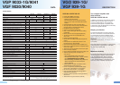
Technical Data
DESCRIPTION
VGO 939-1G/
VGF 939-1G
DATA
Type VGF 9030 VGF 9040 VGP 9033-1G VGP 9041
Order no. 24410108 24410109 24410103 24410054
FORWARD PATH
Frequency range
MHz 85-862 85-862 85-1000 85-862
Gain (at 1000 MHz) dB 33 40 33 40
Return loss dB 19-1.5 dB/oct.
Frequency response (85-1000 MHz at 25 °C) dB ± 0.5
Max. output level according to CENELEC 1) - CTB > 60 dB dBµV 114
Max. output level to CENELEC 1)
-
CSO > 60 dB dBµV 116
Attenuation range, electronically settable in 0.5 dB steps
5
)
dB 0-16 0-15 0-16
Slope range, electronically settable in 0.5 dB steps
5)
dB 0-20 0-15 0-20
Interstage attenuation, settable in 1 dB steps - 0-5 -
Interstage pre-emphasis, electronically settable in 2.5 dB steps dB 2-9 2,5-10 2-9
Noise figure at minimum pre-emphasis dB 6 6.5 6
Adjustment range, sloped at 85 MHz dB - ± 2
Adjustment range, parallel dB - ± 3
Frequency range lower pilot Pu ²)
MHz 85-230 85-230 82.5-230
Frequency range upper pilot Po ²
)
MHz 570-870 570-870
5)
Pilot level (PAL/CW/QAM) dBµV 83-112
Hum modulation ratio at 7 A dB 70 > 67 70
RETURN PATH
Frequency range MHz 5-65
Gain dB 30 28 30
Frequency response at 25 °C
dB ± 0.5 ± 0.3 ± 0.5
Input level density (CINR = 50 dB), at 28 dB gain
6)
dBµV/Hz -9
Dynamic range: CINR > 50 dB, 5-65 MHz, at 28 dB gain
6)
dB 21
Dynamic range: CINR > 50 dB, 5-65 MHz, at 18 dB gain
7)
dB 26
Noise figure dB 6
Attenuation, switchable in 1 dB steps
dB 0-30
Slope, switchable in 7 steps
dB 1-8
ICS switch (attenuation switchable over EMS or
HTE 10 hand-held unit)
dB 0/6/> 45
Hum modulation ratio at 7 A/> 15 MHz dB 60
GENERAL
Voltage supply V
AC
30-72
Power consumption W 21 23
Max. remote feed current per connection A 7
Max. remote feed current in local feeding (power passing) A 10
RF connections
PG 11
Housing protection category
IP 54 IP 67
Ambient temperature range °C -20 to +55
Screening factor Conforms to CENELEC EN 50083-2
Overvoltage protection acc. to IEC 60-2 2 kV (1.2/50 µs)
Dimensions (W x H x D)
mm 240 × 95 × 240
3)
NETWORK MANAGEMENT (optional)
Monitorable/settable parameters
Operational voltage; current; temperature; electronic tuning elements; pilot setting and
alarm; automatic levelling of forward path; automatic presetting of return path; return
path gain; ICS switch; remote inventory data
1)
9 dB slope
2)
Set using HTE 10 hand-held unit
3)
Width incl. hinges: 267 mm
4)
As of device version Bxx from 570-870 MHz
5)
For VGP 9033-1G in 1 dB steps
6)
For VGF 90xx at 30 dB gain
7)
For VGF 90xx at 20 dB gain
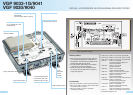
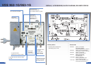
VGP 9033-1G/9041
VGF 9030/9040
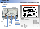
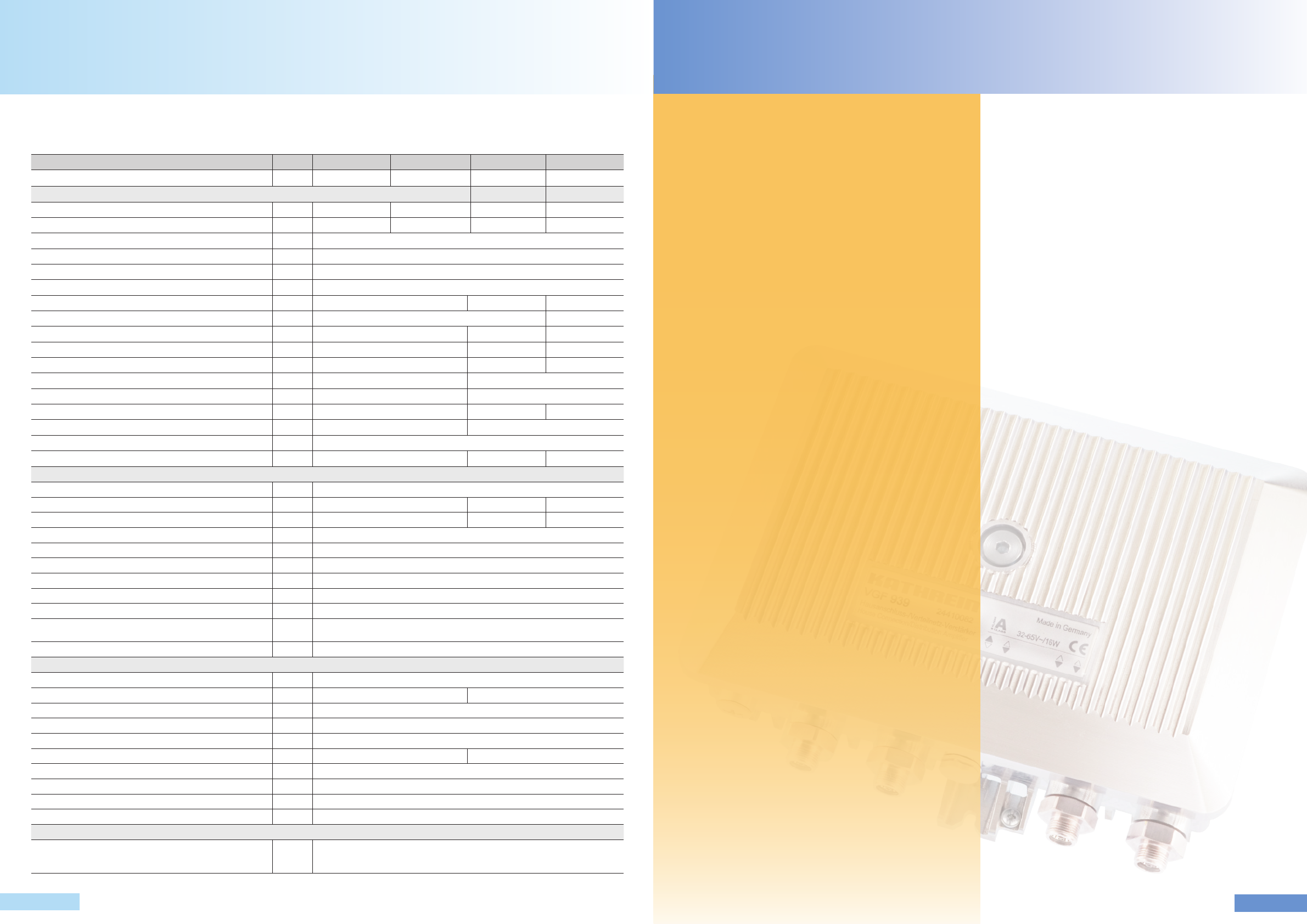
VGO 939-1G/VGF 939-1G
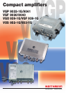
The compact amplifier with
slide switches –
VGO 939-1G/VGF 939-1G
In addition to the devices with electronic setting,
Kathrein offers yet another highly innovative
compact amplifier platform. This particularly
economical series requires no equaliser cards
or attenuation pads. All adjustments can be easily
carried out using slide switches.
Simple, yet effective
The required attenuation and slope values are
set with a combination of several slide switches.
The advantages are obvious. Besides saving
plug-in cards, this allows exact reproduction of
setting values without requiring a measuring
instrument.
Replacement of the device, for example, is thus
much easier.
When slide switches are shifted, a virtually uninter-
rupted signal flow is guaranteed – multimedia
services remain undisturbed.
Maximum reliability
The implemented slide switches fulfil the highest
demands regarding reliability and endurance.
Dual gold-plated contact reeds, increased
contact pressure and a separate catch spring
ensure ultimate reliability of the switches, which
have been proven and tested 100,000 times.
• Latest GaAs-MMIC technology
• Innovative operational concept:
- Settings via slide switches
- Device settings can be reproduced exactly
- Fewer plug-in cards and variable attenuators
needed
• Integrated diplexers allow optimised data
• Very high output level at lowest intermodulation
products (also for interstage attenuation)
• Pluggable loop-through output
• One or two output(s) configurable
• Built-in active return path with various setting
possibilities
• Return path can also be operated passively
•
15 MHz high pass can be activated in the
return path
• Ingress Control Switch (ICS)
• Monitorable with HMS or DOCSIS transponder
(option)
• Insert position for additional functions in the
forward path (e.g. de-emphasis)
• Bi-directional test socket on the amplifier input
• Directional coupler test socket on amplifier output
and in return path
• Test signals can be coupled in for the return path
• LED as function indicator
• Highly efficient switched-mode power supply unit
• Advanced remote power concept in the
VGF 939-1G:
Newly developed remote feed coils
Remote feed current: Max. 7 A per connec-
tion, local insertion max. 10 A totally local insertion max. 10 A totally
Remote feeding possibilities: By choice via
all RF connections or local connector
(power passing)
-
-
-
• Surge absorber on all RF connections and in
switched-mode power supply unit
• Power management: Unused amplifier stage
switch-off for reduced power consumption
• Die-cast housing with PG 11 connectors
• Easy connection of large cable fittings due to
extended thread distance
• Outdoor operation possible, housing protection
class: IP 54
• Test sockets: F-type connectors (internal)