


11
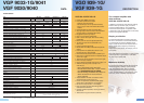
Technical Data
DESCRIPTION
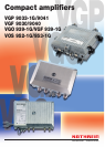
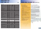
VOS 952-1G/953-1G
DATA
Type VGO 939-1G VGF 939-1G Notes
Order no. 24410101 24410100
Locally fed Remotely fed
FORWARD PATH
Frequency range MHz 85-1000
Gain dB 40
Gain setting range, interstage ³) dB 32-40
Amplitude response dB ±0.5 85-1000 MHz, at 25 °C
Amplitude response (additional, 862-1000 MHz) dB -0.5 at 25 °C
Attenuation setting range, on input
³)
dB 0-26
Pre-emphasis setting range, at input
³)
or interstage dB 0-26 or 0/4/8
Return loss, as of 40 MHz dB 18-1.5/oct.
Noise figure dB 4 at 40 dB gain
Max. operational level: CENELEC raster
¹)
dBµV 116/118
CTB: 60 dB/CSO: 60 dB (pre-emphasis 4 dB)
Hum modulation ratio dB - 60/70 AT 7 A, 5-65/85-1000 MHz
RETURN PATH
Frequency range MHz 5-65
Gain (input stage bridged), active operation dB 30 (21)
Gain, passive operation dB -2
Amplitude response dB 0.5
Attenuation setting range, at input or interstage ³) dB 0/4/8 or 0-16
Pre-emphasis setting range, interstage dB 0/3/6
Ingress Control Switch (ICS) dB 8/> 40 attenuated/switched-off
Max. output level at 30 and 21 dB gain dBµV 107/116 60 dB IMod2/IMod3 (EN 60728-3/50083-5)
Max. output level dBµV 120 According to KDG 1 TS 140 (full system load)
Input level density dBµV/Hz -8 CINR at 50 dB (EN 60728-3/item 4.7)
Dynamic range at 30 dB gain (5-65 MHz) ²) dB 18
Dynamic range at 21 dB gain (5-65 MHz) ²) dB 25
Noise figure dB 6
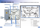
NETWORK MANAGEMENT
Monitorable parameters
Internal voltage supply, internal current drain,
internal temperature, ICS switch
Test sockets
Test socket 1 (on amplifier input), bi-directional dB 20
Test socket 2 (on amplifier output), directional coupler dB 20
Possibility to feed in return path signals
(5-65 MHz); if button is kept pressed, the
incoming return path signal can be measured
Test socket 3 (in return path amplifier), directional coupler dB 10 Attenuation relative to return path input
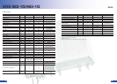
SWITCHED-MODE POWER SUPPLY
Nominal input voltage V
AC
230 32-72
Mains frequency range Hz 50-60
Max. remote feed current A - 7 per input or output
Max. remote feed current, local insertion A - 10
Power consumption (without monitoring) W 17.5 Return path amplifier active
GENERAL
Classification according to KDG 1 TS 140 D(4.4)
Ambient temperature range °C -20 to +55 data-conform operation
RF connections PG 11
Test sockets F-type connector
Housing protection class (to EN 60529) IP 54
Dimensions (W x H x D) mm 238 × 86 × 189
Packing unit/weight pc./kg 1(10)/2.2
1)
CENELEC: 41 channels
2)
When the 15 MHz high pass is connected, the dynamic range increases by 3 dB
3)
Settable in 2-dB steps using slide switches
VGO 939-1G/
VGF 939-1G
• Latest GaAs-MMIC technology
• Innovative operational concept:
- Settings via slide switches
Device settings can be reproduced exactly
Fewer plug-in cards and variable attenuators
needed
-
-
• Very high output level at lowest intermodula-
tion products
• Built-in active return path with various setting
possibilities
• 15 MHz high pass can be activated in the
return path
• Ingress Control Switch (ICS)
• Monitorable with HMS or DOCSIS (option)
• Insert position for additional functions in the
forward path (e.g. de-emphasis)
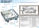
• Bi-directional test socket on amplifier input
with inductive coupling
• Directional coupler test socket on amplifier
output and in return path
• Test signals can be coupled in for the return
path
• Highly efficient switched-mode power supply
unit
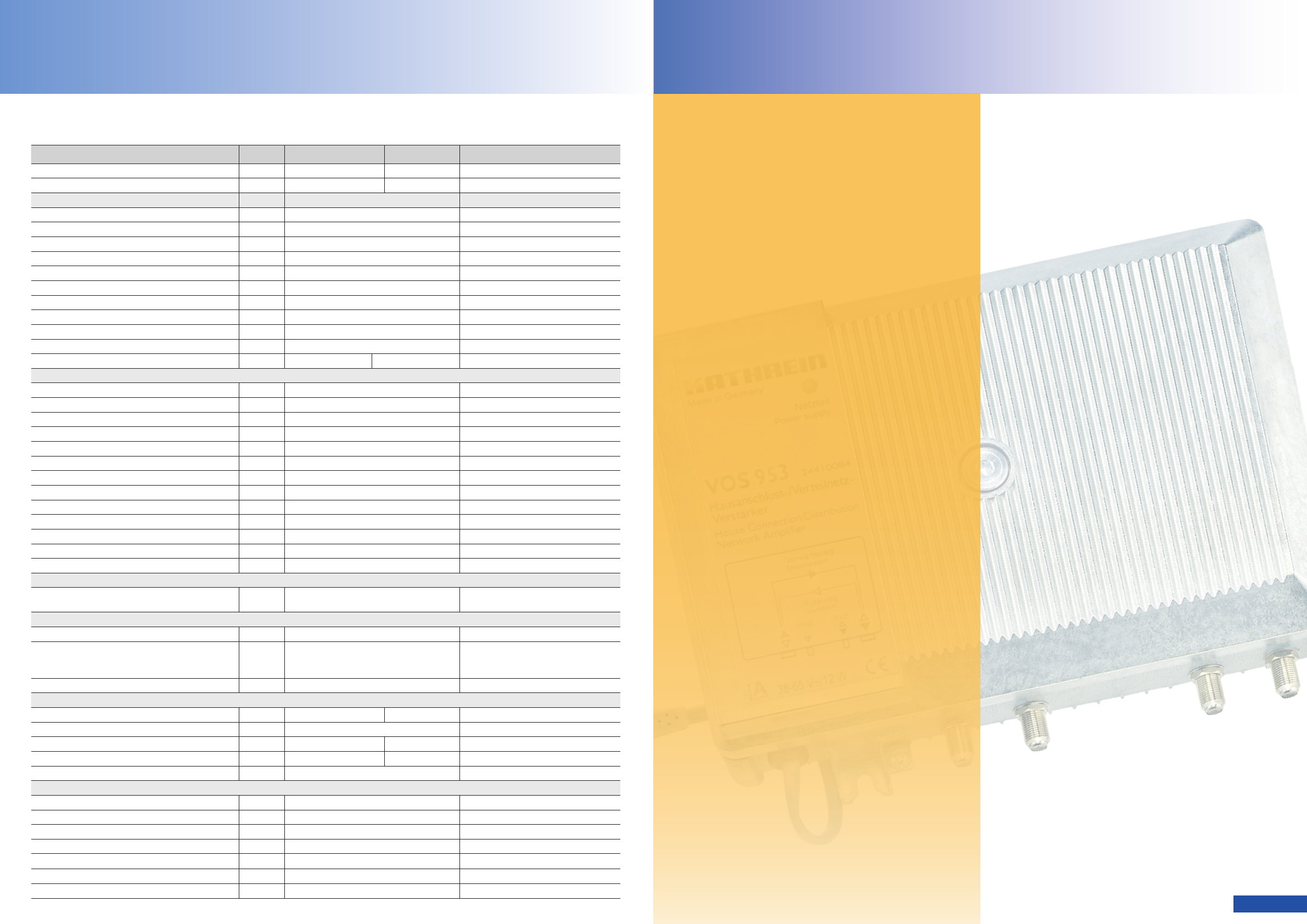
• VOS 952-1G - locally fed, F-type connectors
• VOS 953-1G - remotely fed (auto-supply),
F-type sockets
• Surge absorbers on all RF connections and in
switched-mode power supply unit
• Die-cast housing
• Test sockets: F-type sockets
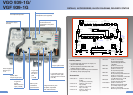
VOS 952-1G/953-1G
House connection amplifiers
The compact, price-optimised house connection
amplifiers 952-1G and VOS 953-1G were designed
for application in modern HFC networks. Great value
was set upon a high dynamic range for Interstage
operation as well as upon a cost-efficient operation
concept with slide switches.
Monitoring via DOCSIS transponder
If fitted with the optional monitoring transponder
TVM 1000/H, the amplifiers VOS 952-1G/953-1G
can be monitored via DOCSIS protocol. Monitoring
with HMS Both amplifiers can be flexibly integrated
into monitoring systems which operate with the
widespread HMS protocol.
Bridgeable diplex filter
Bridging plugs enable variation of the frequency
range between 47-1000 MHz and 85-1000 MHz
making it possible to carry out transmission in
BAND I in the forward path (without return path).
Flexible return path
In the latest generation, the
r
eturn path can be
operated either actively or passively.