


936.3445/-/1108/3.4e
• The units described are intended solely for the installation of satellite receiver systems.
• Any other use, or failure to comply with these instructions, will result in voiding of warranty
cover.
• The units may only be installed in dry indoor areas. Do not mount on or against highly
combustible materials.
• The units should be provided with an equipotential bonding wire (Cu, at least 4 mm
2
).
• The safety regulations set out in the current EN 60728-11 and EN 60065 standards
must be complied with.
• Suitable securing fastenings: Wood screws, max Ø: 4.5 mm
• Connector: HF plug 75 Ω (series F) to EN 61169-24.
Installation and safety instructions
General information on installation
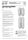
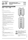
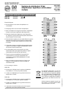
Installation of an amplifi er in a satellite reception system
In principle, the amplifi er can be built into any position in the Sat reception system (see section “System example”).
The following is to be observed:
- the level on the input should fall within the range between 50 to max. 80 dµV and
- the multi-switches following are not to be overdriven
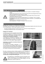
Connection of the amplifi er to other units of the Sat
reception system
The easiest and quickest way to connect the am-
plifi er to, e.g. a EXR 2558/EXR 2998 multi-switch
is by using the optional connector EMU 250
(see picture on right) or the EMU 290 as is required for
the VWS 2991. This enables the units to be connected
to each other directly.
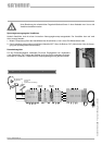
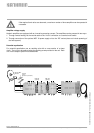
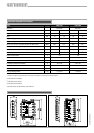
Levelling the amplifi er
In order to defi ne the level, it is recommended to use an
antenna measuring instrument, e.g. MSK 200. You can
adjust the gain in 1-dB increments (see picture on right).
The attenuator affects all Sat-range amplifi er units at the
same time.
To equalise attenuation slopes, such as in long cable
lengths, the amplifi er’s pre-equalisation can be set to 2,
4 and 6 dB. The terrestrial amplifi er is adjusted with its
own attenuator.
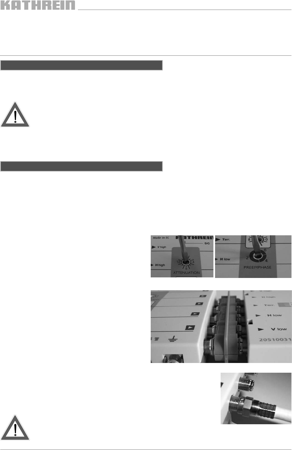
If the units are far apart, it is recommended to use high-quality coaxial cables
(with very high screening values) e.g. LCD 111. If possible, use high-quality F-
type connectors (see picture right) for “crimping” or compression connectors (see
Kathrein catalogue “Satellite and terrestrial antenna products and systems”).
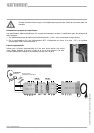
When using coaxial cables, it is especially important to make sure
that the inputs and outputs are correctly assigned to one anoth-
er. The amplifi er’s “V low” output must be connected to the multi-
switch’s “V low” input, etc.