


VENTING
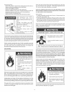
Breathing Hazard ° Catben Monoxide Gas
Install vent system in accordance with
codes.
" Do not operate water heater if hood
damaged.
- High altitude odhce must be installed for
operation above7,700 feet (2,347 m)
o Do not operate ifsoot buildup
" Do not obstruct water heater air intake
with insulating jacket.
- Do not place cheraicd vapor emitting
products near water heater
" Gas and carbon monoxide detectors
are available.
,, Never operate the heater unless it _s
vented to the outdoors and has adequate
air supply to avoid risks of improper
operation, fire, explosion, or asphyxiation
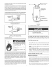
o Make sure the flue baffle and flue restrtctor
ring are properly aligned and inserted on
top of the flue. This can be checked
through the dilution air inlet of the blower
assemb_j.For_ewing, the AirIntake screen
d the blower assembly will have to be
removed Replaceafterthe check is made
Breathing carbon monoxide can cause brain damage or death
Always read and understand instruction manual
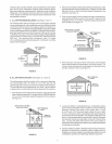
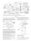
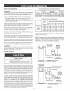
The vent system must terminate so that proper clearances are
maintained as cited in local codes or the current edition of the National
Fuel Gas Code, ANSi Z223.1/NFPA54, 7.3.4e and 7.8a,b, as follows:
1. The exit terminals of a mechanical vent system shall be not less
than 7 feet (2. ! 3 m) above grade when located adiacent to public
walkways, see Figure 23.
2. A venting system shall terminate at least 3 feet (91 cm) above any
forced air inlet located within 10 feet (3.1 m), see Figure 23.
3. The venting system shall terminate at least 4 feet (1.2 m) below, 4
feet (! .2 m) horizontally from or, 12 in. (30 cm) above any door,
window or gravity air inlet into any building.
The manufacturer also recommends that the vent termination should
not be installed closer than 3feet (91 cm) from an inside corner of an
L shaped structure and not be less than 12 in. (30 cm) above grade.
The vent shall terminate a minimum of 12" (30.5 cm) above expected
snow, all level to prevent blockage of vent termination, see Figure 23.
4. Incold climates, itis recommended that vent termination not be mounted
directly above orwithin 3feet (91 cm) horizontally from an oiltank vent or
gas meter to avoid potential freeze-up from condensation, see Figure 23.
Plan the vent system layout so that proper clearances are maintained
from plumbing and wiring.
Vent pipes serving power vented appliances are classified by building
codes as "vent connectors". Required clearances from combustible
materials must be provided inaccordance with information inthis manual
under FACTS TO CONSIDER ABOUT THE LOCATION and VENT
TERMINAL INSTALLATIONS, and with the National Fuel Gas Code and
local codes.
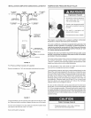
VENT TERMINAL INSTALLATION
After the point of termination has been determined, use the cover
plate as a template to mark the hole for the vent pipe to insert
through the wall. BEWARE OF CONCEALED WIRING AND PIPING
INSIDE OFWALL
If the Vent Terminal is being installed on the outside of a finished
wall, it may be easier to mark both the inside and outside walk
Align the holes by drilling a hole through the center of the template
from the inside through to the outside. The template can now be
positioned on the outside wall using the drilled hole as a centering
point for the template.
A) MASONRY SIDE WALLS
Chisel an opening approximately one half inch larger than the
marked circle.
B) WOODEN SIDE WALLS
Drill a pilot hole approximately one quarter inch outside of the
marked circle. This pilot hole is used as a starting point for a
saws=all or sabre saw blade. Cut around the marked circle staying
approximately one quarter inch outside of the line. (This will allow
the vent pipe to easily slide through the opening. The resulting
gap will be covered up by the vent terminal cover plates.) Repeat
this step on inside wall if necessary.
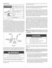
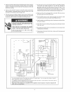
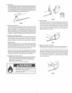
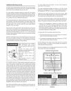
When the vent piping cannot pass through an outside wall at a
height greater than or equal to 12" above the ground (or above
snow accumulation level), then the installation can be modified as
shown below.
12"MIN. ABOVE
GROUNDORSNOW
ACCUMULATIONLEVEL
FIGURE22.
18