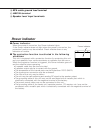
4
Controls
Operations of the following control and switches are required in accordance with
the center unit and speakers connected with this unit.
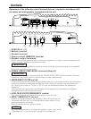
POWER IN
FUSE(20A)
BATT
GND
FUSE(20A)
P.CON(REMOTE)
SPEAKER OUTPUT
1 2 3
456
MONO
POWER AMPLIFIER
L
25Hz
15Hz
INFRASONIC
OFF
INPUT
SENSITIVITY(V)
LPF
FREQUENCY(Hz)
GND
R
LINE IN
0.3
0.5
1
2
3
4
50.2
150
100
70
50 200
LEFT RIGHT
SPEAKER LEVEL INPUT
@7 8 9 0 !
20
20
SERVO ΙΙ
∑
SERVO ΙΙ
∑
1
FUSE (20 A
×
2)
2
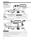
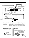
Battery terminal
3
Ground terminal
4
Power control (REMOTE) terminal
5
Speaker output terminals
As this unit accepts speakers with a minimum impedance of 2 ohms, connect speakers with
2-ohm or higher impedance to these terminals.
The rated input of the speakers should be no less than the maximum output of the amplifier.
Otherwise malfunction may result.
6
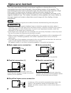
SIGMA SERVO FEED BACK terminals (See p.8)
Be sure to make proper connections to the SIGMA SERVO FEED BACK terminals. Incorrect
connection may result in lack of sound output or other malfunctions.
7
INFRASONIC FILTER switch
Ultralow frequencies that cannot be reproduced even by a subwoofer speaker do not become
sound but become unnecessary oscillations, which affect the sound by causing distortion,
etc. Setting this switch to "15 Hz" or "25 Hz" cuts the frequencies below the respective
frequency.
This improves the reproduction performance of the speakers by eliminating unnecessary
oscillations which will not become sound.
8
LOW PASS FILTER FREQUENCY control
This control adjusts the frequency band output from this unit.
9
INPUT SENSITIVITY control
Set this control according to the pre-output level of the center unit
connected with this unit, or to the maximum power output of the
genuine-accessory car stereo.
Use the diagram on the right as a guide.
For the pre-output level or the maximum power output, refer to the
“Specifications” in the instruction manual of the center unit.
NOTE
2CAUTION
2CAUTION
0.3
0.2
0.5
1
2
3
4
5
(V)
(W)
25
15
10


