


English
|
37
P.CONT
ANT.CONT
1
2
3
4
5
6
7
8
1
2
3
4
5
6
7
8
SUB
WOOFER
MUTE
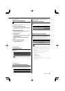
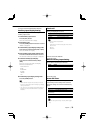
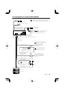
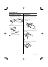
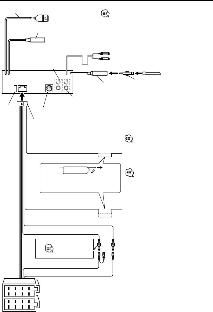
Connecting Wires to Terminals (KDC-W6534U)
Battery wire (Yellow)
Ignition wire (Red)
FM/AM antenna
input
Antenna Cord (ISO)
Antenna Conversion Adaptor
(ISO–JASO) (Accessory3)
To connect the Kenwood
navigation system, consult
your navigation manual.
Wiring harness
(Accessory1)
If no connections are made, do
not let the wire come out from
the tab.
Power control/ Motor
antenna control wire
(Blue/White)
TEL mute wire (Brown)
Connect either to the power
control terminal when using the
optional power amplifier, or to
the antenna control terminal in
the vehicle.
Connect to the terminal that
is grounded when either the
telephone rings or during
conversation.
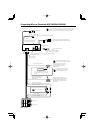
A-–7 Pin (Red)
A–4 Pin (Yellow)
Connector A
Connector B
Fuse (10A)
See next page
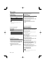
Front left output (White)/
Front right output (Red)
To connect these leads, refer to
the relevant instruction manuals.
To External Display/ Steering remote
To Kenwood disc changer/ External optional accessory
AUX right input (Red)
AUX left input (White)
• Do not remove the cap when you do not use the USB
cable. The connector will cause the unit to malfunction if
it gets in touch with any metallic part of the vehicle.
Rear left output (White)/Sub
Woofer left output (White)
Rear right output (Red)/Sub
Woofer right output (Red)
USB connector
To USB device