


— 14 —
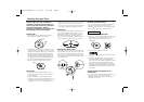
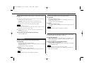
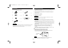
CD AUTO CHANGER CONTROLLER
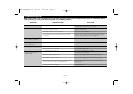
REP
RDM
3
-
+
4¢PWR
'
M.RDMM.RDM D.REPD.REP
TRACK DISC
8
/
D.D.SCNSCN
MHzMHz
DISCDISC
TRACKTRACK
FREQFREQ
LEVELLEVEL
9
0
4
5
0
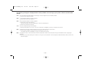
To prevent fire when the ignition wire (Red) or battery wire
(Yellow) is short-circuited by coming into contact with the
vehicle chassis (ground), only connect the power supply after
making the fuse box connections.
Be sure to press the reset button after installation.
Do not install an antenna of radio equipment or distribute the
antenna wire near the changer output wire, for this could
cause malfunction with this unit.
NOTE
2CAUTION
2WARNING
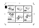
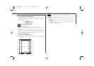
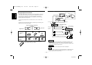
Connecting Wires to TerminalsInstallation Procedure
English
Control output
Control input
CD auto -
changer
input
Changer connection wire 4
FM modulator unit
FM/AM antenna input
FM/AM antenna output
Ground wire (Black)
- (To car chassis)
Car fuse box
ACC
Ignition key
switch
Antenna plug
for automobile
Output
Car stereo
with FM tuner
Battery
Display unit
Battery wire + (Yellow)
Ignition wire
+ (Red)
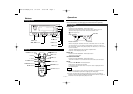
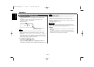
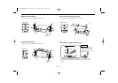
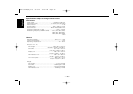
Angle adjustment switches
■
The angle adjustment switches on the both saides of the unit
are to be set according to the angle of installation of the CD
auto changer. Set both of the two switches to the same
position. If the switches are not set properly, sound skip or
other malfunction may occur.
Set the angle adjustment switches with a coin or other flat
object.
Change the switch step by step by detaching and reusing the
object at the end of each step.
Right side
Left side
Angle adjustment switches
9090
0
45
90
0
45
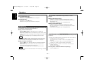
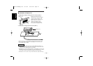
Installation
angle
0°~5° 40°~50°
85°~90°
90
0
45
90
0
45
90
0
45
Angle
adjustment
switch
position
• It is not possible to install at an angle of
40°~50° if only 1 is used.
0!@#$
CD auto-changer
KDC-C519FM(M)/U.S 02.9.24 10:01 AM Page 14