


8 English
L
R
L
R
L
R
L
C
C
L
R
L
R
L
C
C
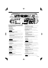
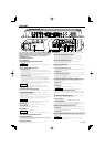
A
B
Bch Ach
INPUT
SENSITIVITY(V)
INPUT
SENSITIVITY(V)
HPF
FREQUENCY(Hz)
HPF
FREQUENCY(Hz)
LPF
FREQUENCY(Hz)
4
0.2(MAX)(MIN)5
3
2
1
0.5
0.3
4
0.2(MAX)(MIN)5
3
2
1
0.5
0.3
50 200
50 200
150
100
70
50 200
150
100
70
150
100
70
FILTER
HPF
LPF
OFF
AMPCONT
ON
OFF
ISF
ON
OFF
HPF
ON
OFF
OPERATION
MONO(Lch)
STEREO
OPERATION
MONO(Lch)
STEREO
L
R
L
R
L
R
L
R
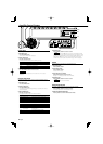
A
B
L
R
L
R
L
R
L
R
A
B
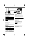
Bch Ach
INPUT
SENSITIVITY(V)
INPUT
SENSITIVITY(V)
HPF
FREQUENCY(Hz)
HPF
FREQUENCY(Hz)
LPF
FREQUENCY(Hz)
4
0.2(MAX)(MIN)5
3
2
1
0.5
0.3
4
0.2(MAX)(MIN)5
3
2
1
0.5
0.3
50 200
50 200
150
100
70
50 200
150
100
70
150
100
70
FILTER
HPF
LPF
OFF
AMPCONT
ON
OFF
ISF
ON
OFF
HPF
ON
OFF
OPERATION
MONO(Lch)
STEREO
OPERATION
MONO(Lch)
STEREO
L
R
L
R
L
R
L
R
A
B
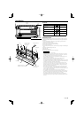
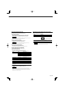
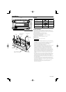
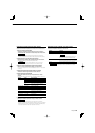
System examples
■ Tri-mode
CENTER UNIT
(High pass)
Subwoofer
(L + R) (Bridged)
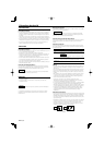
Principle of Tri-mode
Method of frequency band division using a coil and capacitor…in case of 6dB/oct. slope.
L
C
0 dB
-3 dB
Coil (L):
Passes low frequencies and blocks high
frequencies. (Low pass)
Capacitor (C):
Passes high frequencies and blocks low
frequencies. (High pass)
Crossover Frequency
Frequency
159000
C= (µF)
fc × R
159 x R
L= (mH)
fc
fc=Cut of Frequency (Hz)
R=Speaker Impedance (Ω)
Example:
When it is required to set a crossover frequency of 120 Hz using speakers with an
impedance of 4 ohms.
Prepare commercially-available coil and capacitor with the closest ratings to the
results calculated from the formula above. The capacitor rating should be as close as
possible to 331.25 (µF) and the coil rating should be as close as possible to 5.3 (mH).
2CAUTION
• If you wish to bridge-connect a speaker, the speaker impedance must be no less
than 4 ohms. Connecting a speaker with an impedance lower than 4 ohms may
damage the unit.
• Be sure to connect capacitors to speakers to which high frequencies will be passed.
Failure to do so will result in a drop of the combined impedance with the subwoofer.
• Ensure that the withstand voltage and current ratings of the capacitors (C) and coils
(L) are sufficient.
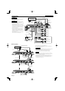
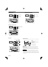
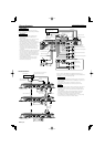
CENTER UNIT
■ 4-channel system ■ High-power 2-channel system
Right speaker (Bridged)
Left speaker (Bridged)
■ 2-channel + Subwoofer system
Subwoofer
(Bridged)
CENTER UNIT
CENTER UNIT
Right speaker (High pass)
Left speaker (High pass)
Front Right speaker
Front Left speaker
Rear Right speaker
Rear Left speaker