


2
COMPVT65SUBWOOFER
3
MOUNTING
If you are replacing factory speakers in their original locations, you may have to enlarge the speaker
cut-outs and pre-drill new screw holes using a 7/64” (2.5mm) bit. Custom mounting locations will require
more preparation and work. In either case, make sure the speaker will not interfere with the trunk and
door opening and closing mechanisms, and the screws will not puncture the fuel tank, wiring, or interfere
with any other mechanical parts on the underside of the mounting surface. Cycle the windows all the way
down and up.
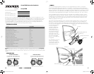
If the speaker cut-out locations require you to cut metal, avoid structural metal and braces. If the door
body and panel cannot support the weight of the speaker, an optional reinforcing ring (thin piece of wood
or Medium Density Fiberboard) may be sandwiched between the panels. Mount the speaker to the
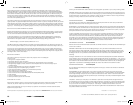
vehicle as outlined in Figures 2/3.
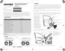
It may be necessary to run wire through the door jamb. The speaker wire should be kept away from sharp
edges and avoid the possibility of getting pinched by the door. An existing grommet in the door jamb is
the ideal place to run the speaker wire. If the factory hole and grommet do not exist or are inaccessible,
you must drill a hole to run the speaker wire through the door jamb. Be careful not to drill into other wiring
or exiting door mechanisms. Any time a wire is run through a hole, it is necessary to insert a rubber or
plastic grommet to protect the
wire from damage as outlined
below.
We recommend using genuine
Kicker accessories and wiring to
get the best performance from
your CompVT 65 subwoofer.
COMPVT65 SUBWOOFER Owner’s Manual
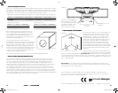
Kicker CompVT 65 subwoofers were specially designed for “Livin’ Loud” in the harsh automotive
environment. CompVT subwoofers are versatile and surpass the competition in a sealed box, but can also
be mounted in free air applications and factory cutout locations. The small diameter of the CompVT 65
subwoofers make them ideal for custom installations and space-limited applications. They are made of
advanced materials and construction techniques to maintain optimal performance for years to come.
WIRING
Authorized KICKER Dealer:
Purchase Date:
Speaker Model Number:
Speaker Serial Number:
Model CompVT65
Nominal Impedance [Zn], ohm [per coil] 2 or 4
Resonance Frequency [fs], Hz 53.9
Power Handling Watts, Peak (RMS) 300 (150)
Sensitivity [SPLo], dB @ 1W, 1m 84.6
Total Q-Factor [Qts] .667
Mechanical Q-Factor [Qms] 9.426
Electrical Q-Factor [Qes] .718
Effective Excursion [EXmax™], in. (mm) .17 (4.3)
DC Resistance [Re], ohm 2.05
Equivalent Volume [Vas], ft
3
(L) .328 (9.28)
Net Displacement, in
3
(cc) 21 (344)
Outer Frame Dimension, in (cm) 6-13/16 (17.3)
Mounting Depth, in (cm) 2-7/8 (7.3)
Hole Cut-Out Diameter, in (cm) 5-9/16 (14)
CompVT65
Models:
SPECIFICATIONS
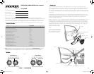
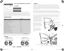
Door body
Reinforcing ring (optional)
Door panel
Speaker cutout
CompVT
Door jamb
Woofer mounting hole
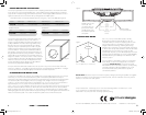
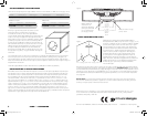
To woofer terminals
From amplifi er or source unit
Rubber grommets
Note: All specifi cations and performance fi gures are subject to change. Please visit www.kicker.com for the most
current information. To get the best performance from your new KICKER Subwoofer, we recommend using genuine
KICKER Accessories and Wiring. Please allow two weeks of break-in time for the subwoofer to reach optimum
performance.
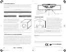
Series Wiring
Parallel Wiring
Two 2 Woofers = 4 Load
Two 4 Woofers = 8 Load
Two 2 Woofers = 1 Load
Two 4 Woofers = 2 Load
Figure 3
Figure 2
Figure 1
2010 CompVT 65 c01.indd 2-32010 CompVT 65 c01.indd 2-3 9/18/2009 10:16:22 AM9/18/2009 10:16:22 AM