


2
COMPVT SUBWOOFER
3
A
B
C
The Kicker CompVT subwoofers were specially designed for “Livin’ Loud” out in the harsh automotive
environment. CompVT subwoofers are versatile and surpass the competition in a sealed or vented box.
The ultra-thin mounting depth makes the CompVT subwoofers ideal for custom installations and space-
limited applications. They are made using advanced materials and construction techniques to maintain
optimal performance for years to come.
WIRING
SEALED ENCLOSURE APPLICATIONS
The CompVT generates more sound pressure than competing subwoofers on the market and excels
when used in the recommended sealed boxes. These sealed enclosure designs give the smoothest
response with increased energy at the lowest frequencies, 20 to 40Hz. These designs deliver massive
amounts of highly-accurate bass and can be driven with punishing levels of amplifi er power.
The CompVT high performance suspension
system can operate in a larger sealed
enclosure. This maximum enclosure volume
application is ideal for SQ (ultra sound quality)
installations. The SQ enclosure generates
a very fl at response curve and superbly
extends the subbass response. CompVT
subwoofers perform well in any size sealed
enclosure between the Compact and SQ
volume recommendations. These systems
will exhibit benefi ts of both designs: Compact
produces high-impact bass, and SQ
generates low bass frequency protraction.
Overall, the system will sound more like the
recommended enclosure design it is closest
to in enclosure volume. These enclosure
recommendations have been calculated with
the airspace inside the enclosure and include
the displacement of the woofer. All sealed
enclosure airspace should be fi lled to 50%
loose poly-fi l (polyester fi berfi ll) stuffi ng. Do
not make the airspace greater than the SQ maximum enclosure volume, recommendation.
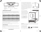
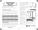
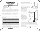
To make the most effi cient use of space when building the compact sealed enclosure for your CompVT
subwoofer, you must use the included clearance plate. The clearance plate allows the CompVT
subwoofer to sit recessed within the back panel of the subwoofer box to minimize the enclosure’s
depth. The clearance plate must seal tightly. First, use a plunging router, straight-cut bit, and a circle jig
to create a 1/16” (2mm) deep recess with an outer diameter of 6 1/2” (16.7cm) and an inner diameter
of approximately 5” (12.7cm). Center the recess behind the subwoofer on the back panel. Then, cut
a 5 1/4” (13.3cm) diameter hole in the center of the recess all the way through the back panel. Using
the clearance plate as a reference, drill the six screw holes with a #29 (0.136”, 3.5mm) drill bit. Next,
countersink each screw hole using a 1/4” (6mm) drill or countersinking bit so the clearance plate will
fi t tightly against the back panel. Remove the paper backing from the foam gasket and adhere it to the
inside of the clearance plate. Then, fasten the clearance plate to the box with six #8 screws.
COMPVT SUBWOOFER Owner’s Manual
Authorized KICKER Dealer:
Purchase Date:
Speaker Model Number:
Speaker Serial Number:
Model CompVT8 CompVT10 CompVT12
Nominal Impedance [Zn], ohm [per coil] 2 or 4 2 or 4 2 or 4
Resonance Frequency [fs], Hz 49.2 32.7 32.7
Power Handling Watts, Peak (RMS) 400 (200) 800 (400) 800 (400)
Sensitivity [SPLo], dB @ 1W, 1m 84.8 87.2 87.1
Total Q-Factor [Qts] .565 .440 .518
Mechanical Q-Factor [Qms] 10.641 9.56 10.16
Electrical Q-Factor [Qes] .597 .461 .546
Effective Excursion [EXmax™] in (mm) .28 (7.1) .36 (9.2) .39 (9.8)
DC Resistance [Re], ohm 2.15 2.13 2.16
Equivalent Volume [Vas], ft
3
(L) .364 (10.32) 1.3 (37.14) 2.15 (61)
Net Displacement, in
3
(cc) 30.4 (497) 48.2 (790) 52.4 (860)
Outer Frame Dimension, in (cm) 8 1/2 (21.6) 10-11/16 (27.1) 12-5/8 (32)
Mounting Depth, in (cm) 3-7/16 (8.73) 4-1/4 (10.8) 4-3/8 (11.1))
Hole Cut-Out Diameter, in (cm) 7-1/16 (17.8) 9-3/16 (23.3) 11 (28.1)
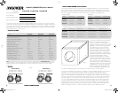
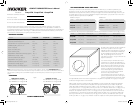
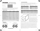
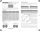
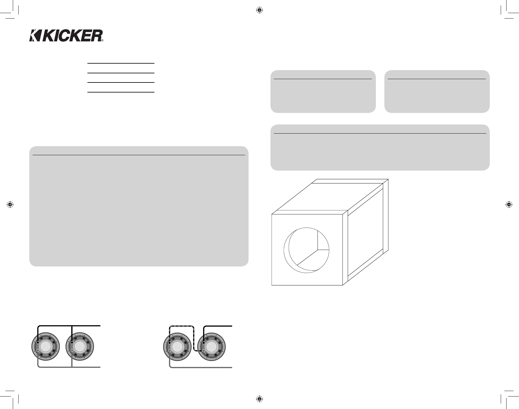
Model Volume ft
3
(L) Panel A in. (cm) Panel B in. (cm) Panel C in. (cm)
CompVT8 .4 ft
3
(11.3L)
13.5x24.5 (34.3x62.2) 2.5x24.5 (6.4x62.2) 2.5x12 (6.4x30.5)
CompVT10 .8 ft
3
(22.7L) 18x30.5 (45.7x77.5) 3x30.5 (7.6x77.5) 3x16.5 (7.6x41.9)
CompVT12 1 ft
3
(28.3L) 18x36 (45.7x91.4) 3.125x36 (7.9x91.4) 3.125x16.5 (7.9x41.9)
Model Volume ft
3
(L) Power Handling
CompVT8 .4 ft
3
(11.3L) 200W RMS
CompVT10 .8 ft
3
(22.7L) 400W RMS
CompVT12 1 ft
3
(28.3L) 400W RMS
Model Volume ft
3
(L) Power Handling
CompVT8 1.8 ft
3
(51L) 200W RMS
CompVT10 3 ft
3
(85L) 300W RMS
CompVT12 4.6 ft
3
(130L) 300W RMS
CompVT8 / CompVT10 / CompVT12
Models:
SPECIFICATIONS
Panel Dimensions for Compact Sealed Enclosures using 3/4” (1.9cm) thick MDF (See Figure 2)
Sealed Compact
Sealed SQ
Note: All specifi cations and performance fi gures are subject to change. Please visit www.kicker.com for the most
current information. To get the best performance from your new KICKER Subwoofer, we recommend using genuine
KICKER Accessories and Wiring. Please allow two weeks of break-in time for the subwoofer to reach optimum
performance.
Figure 1
Figure 2
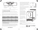
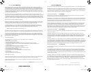
Series Wiring
Parallel Wiring
Two 2 Woofers = 4 Load
Two 4 Woofers = 8 Load
Two 2 Woofers = 1 Load
Two 4 Woofers = 2 Load
2010 CompVT d01.indd 2-32010 CompVT d01.indd 2-3 11/4/2009 5:06:31 PM11/4/2009 5:06:31 PM