


Operation
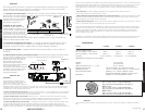
Your Kicker ZX.1 series amplifier has three rotary controls on top and one switch on the end-panel.
Before turning on the system for the first time, turn the three rotary controls on the top of the amplifier
to the full counter-clockwise position.
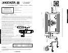
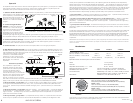
1. SubsonicFilterSwitch The subsonic filter switch located on the end-panel utilizes an internal
12dB per octave at 25 Hz high-pass
crossover in the ON position. The
setting for this control is subjective;
the ON position is a good place to
start. Never change the subsonic filter
switch “ON/OFF” setting with the
audio system on! See Figure 1.
2. InputGainControl The input gain
control is not a volume control. It
matches the output of the source unit
to the input level of the amplifier. Turn
the source unit up to about 3/4 volume (if the source unit goes to 30, turn it to 25). Next, slowly turn
(clockwise) the gain on the amplifier up until you can hear audible distortion, then turn it down a little.
3. BassBoostControl The bass boost control is designed to give you increased output 0 - 18dB
at 40 Hz. The setting for this control is subjective. If you turn it up, you must go back and adjust the
input gain control to avoid clipping the amplifier.
4. CrossoverControl The setting for this control is subjective; 80Hz is a good place to start.
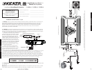
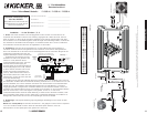
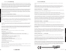
5. RemoteBass(Level Control) With the remote bass level control you have the ability to control the
level of the subwoofer(s) remotely by controlling the output level of one or more ZX series amplifiers. To
mount the remote bass level control, simply screw the metal bracket to the chosen location. Then slide
the housing onto the bracket until it
snaps into place. Run the cable from
the controller to the “Remote Bass”
jack on the amplifier chassis.
TroubleShooting
If your amplifier does not appear to
be working, check the obvious things
first such as blown fuses, poor or
incorrect wiring connections,
incorrect setting of crossover switch
and gain controls, etc. There are two
LEDs on the top of your Kicker ZX
series amplifier, one green and one
red. When the green LED is lit this indicates the amplifier is turned on and no trouble exists. If the green
LED turns off and the red LED is lit, this indicates that the protection circuitry (SORT) is engaged.
Green LED off, no output? With a Volt Ohm Meter (VOM) check the following: 1) +12 volt power
terminal (should read +12V to +16V) 2) Remote turn-on terminal (should read +12V to +16V)
3) Check for reversed power and ground connections 4) Ground terminal, for proper conductivity.
Green LED on, no output? Check the following: 1) RCA connections 2) Test speaker outputs
with a “known” good speaker. 3) Substitute source unit with a “known” good source unit. 4) Check
for a signal in the RCA cable feeding the amplifier with the “AC” test position selected on the VOM
meter.
Red LED on, no output? 1) Amplifier is very hot. Thermal protection is engaged. Test for proper
impedance at the speaker terminals with a VOM meter (see the diagrams in this manual for minimum
recommended impedance and multiple speaker wiring suggestions). Also check for adequate airflow
around the amplifier. 2) Amplifier shuts down only while vehicle is running. Voltage protection
circuitry is engaged. Voltage to the amplifier is not within the 9-16 volt operating range. Have the
vehicle's charging and electrical system inspected. 3) Amplifier will only play at low volume levels.
Short circuit protection is engaged. Check for speaker wires shorted to each other or to the vehicle
chassis. Check for damaged speakers, or speaker(s) operating below the minimum recommended
impedance.
No or low output? 1) Check the balance and fader control on source unit 2) Check the RCA
(or speaker input) and speaker output connections
Alternator noise-whining sound with engine’s RPM? 1) Check for damaged RCA
(or speaker input) cable 2) Check the routing of RCA (or speaker input) cable 3) Check the source
unit for proper grounding 4) Check the gain settings and turn them down if they are set too high.
Reduced bass response? Check system phasing by reversing a speaker connection from
positive to negative on the stereo/subwoofer channel(s); if the bass improves, the speaker was out
of phase.
If you have more questions about the installation or operation of your new KICKER product, see the
Authorized KICKER Dealer where you made your purchase. For more advice on installation, click on the
SUPPORT tab on the Kicker homepage, www.kicker.com. Choose the TECHNICAL SUPPORT tab,
choose the subject you are interested in, and then download or view the corresponding information.
Please E-mail support@kicker.com or call Technical Services (405) 624-8583 for unanswered
or specific questions.
CAUTION: When jump starting the vehicle, be sure that connections made with jumper cables are
correct. Improper connections can result in blown amplifier fuses as well as the failure of other critical
systems in the vehicle.
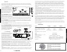
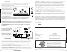
Performance
Model ZX1000.1 ZX1500.1 ZX2500.1
RMS Power in Watts
@14.4V, 4Ω Mono ≤1.5% THD+N 500 x 1 750 x 1 1250 x 1
@14.4V, 2Ω Mono, ≤1.5% THD+N 1000 x 1 1500 x 1 2500 x 1
Length: 16 3/4” (425mm) 20” (507mm) 27 1/2” (699mm)
Specifications common to all models:
Height: 2 1/8” (54mm)
Width: 9 5/8” (244mm)
Frequency Response, + 0 / - 1 dB: 20 Hz - 200 Hz
Signal-to-Noise Ratio: >95 dB, a-weighted, re: rated power
Input Sensitivity: 125 mV - 5 V low level, 250 mV - 10 V high level
Electronic Crossover: Variable Low-Pass, 50 - 200Hz, 24dB per octave
Defeatable High-Pass 12 dB per octave @ 25 Hz
Bass Boost: Variable 0 to +18 dB boost @ 40 Hz
ZX.1AMPLIFIER
4 5
PERFORMANCE
OPERATION
-
+
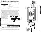
Figure 3
Crossover Control
50 - 200Hz, 24dB/Oct
Input Gain Control
Low Level: 125mV - 5V, High Level: 250mV - 10 V
Bass Boost Control
0 to +18dB boost @ 40Hz
INPUT
REMOTE
BASS
RL
+-
OUTPUT
RL
HI-LEVEL
INPUT
+ - - +
ON OFF
SUB SONIC
Figure 4
Mount the metal bracket
Back View
Side View
4 Conductor
Phone Cable
Slide the housing until it snaps into the metal bracket
Model ZX1000.1
500 x 1 @ 4 ohms, 14.4Vdc, 1% THD, CEA-2006 (Watts)
Signal to Noise Ratio -60 CEA-2006 (ref: 1W, A-weighted)
Model ZX1500.1
750 x 1 @ 4 ohms, 14.4Vdc, 1% THD, CEA-2006 (Watts)
Signal to Noise Ratio -58 CEA-2006 (ref: 1W, A-weighted)
Model ZX2500.1
15
00 x 1 @ 4 ohms, 14.4Vdc, 1% THD, CEA-2006 (Watts)
Signal to Noise Ratio -46 CEA-2006 (ref: 1W, A-weighted)