


2
Manual No. 701-170M 12/05/06
Land Pride
Assembly Instructions
■
Head Rest Assembly
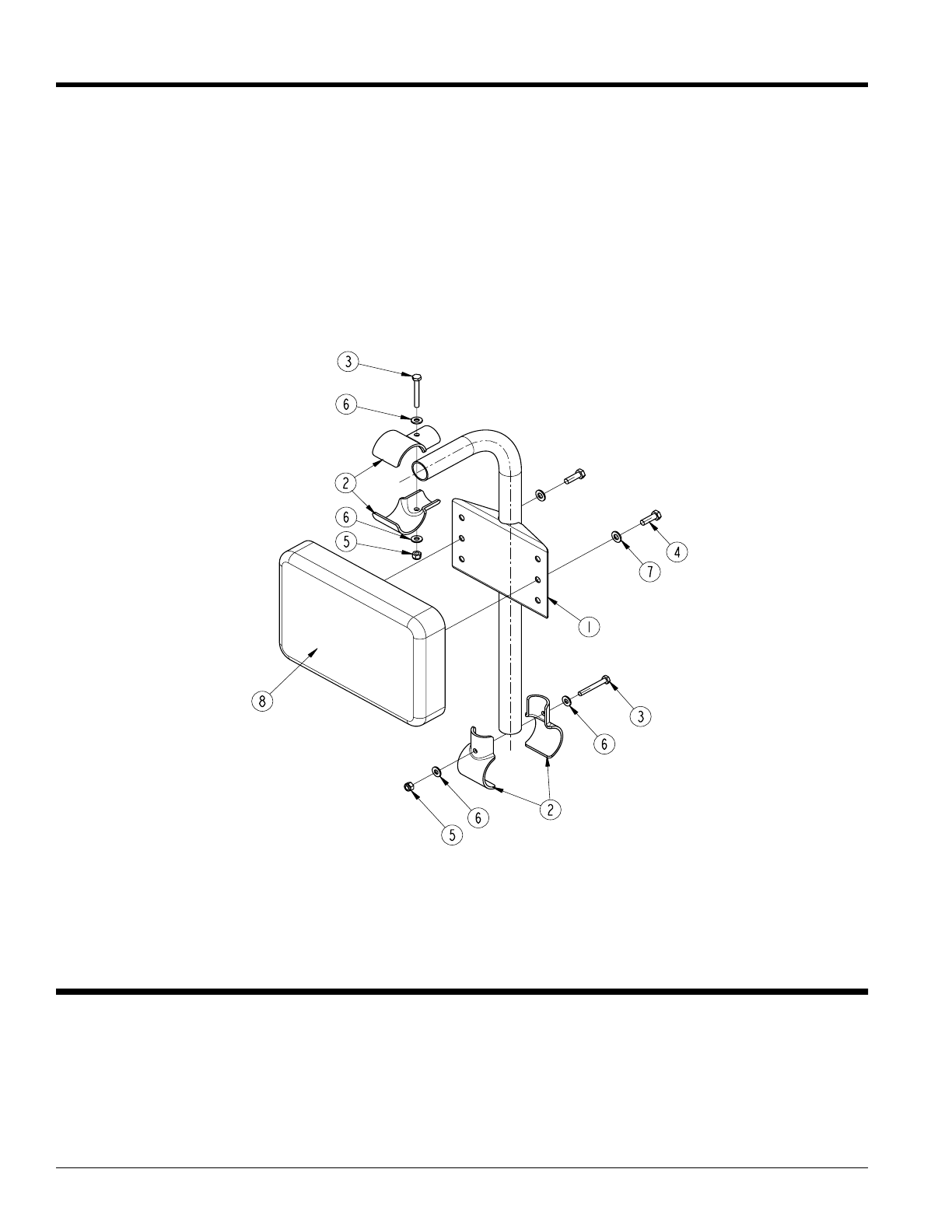
Figure 1
24822
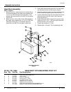
Kit No. 701-169A HEAD REST WITH MOUNTING POST KIT
Item Qty. Part No. Part Description
1 2 700-420H HEAD REST MOUNTING POST
2 8 700-500d JOINT PLATE
3 4 802-152C HHCS 1/4-20X2 GR5
4 4 802-738C HHCS 5/16-18 X 1 GR5
5 4 803-255C NUT HEX NYLOCK 1/4-20
6 8 804-007C WASHER FLAT 1/4 SAE PLT
7 2 804-036C WASHER FLAT 5/16 SAE PLT
8 2 840-179C HEAD REST WITH MOUNTING HARDWARE #4 & #7
1 701-170M MANUAL, HEAD REST WITH MOUNTING POST
Head Rest Assembly
Refer to Figure 1:
1. Behind the driver, attach bottom joint halves (#2) to
the 4-Post Accessory Bar lower cross member with
1/4"-20 x 2" GR5 hex head cap screw (#3), 2- flat
washers (#6) and nylock hex nut (#5). Do not tighten
nylock nuts.
2. Attach top joint halves (#2) to the 4-Post Accessory
Bar upper cross member with 1/4"-20 x 2" GR5 hex
head cap screws (#3), 2- flat washers (#6) and
nylock hex nuts (#5). Do not tighten nylock nuts.
3. Insert head rest mounting post (#1) into the bottom
joint halves and then into the top joint halves.
4. Adjust joint halves to center the head rest behind the
driver’s head and tighten nylock nuts to 8 ft-lbs.
5. Locate a desirable height that will protect the driver’s
head using two of the six holes in the head rest
mounting post (#1).
6. Attach head rests (#8) to the mounting post at that
height with 5/16"-18 x 1" GR5 hex cap screws (#4)
and flat washers (#7) as shown.
7. Tighten cap screws to 11 ft-lbs.
8. Repeat steps 1 through 7 for the passenger side.