


4
Liebert Corporation
1050 Dearborn Drive
P.O. Box 29186
Columbus, OH 43229
Telephone: 1-800-877-9222
Facsimile: 1-614-841-6022
www.liebert.com
© 2004 Liebert Corporation
All rights reserved throughout the world. Specifications sub-
ject to change without notice.
® Liebert and the Liebert logo are registered trademarks of
Liebert Corporation. All names referred to are trademarks or
registered trademarks of their respective owners.
SL-25246 (10/04) Rev. 0
if they get failure during operation. For 1+1 sys-
tems, this settings needs to be set to 1.
System Startup
1. Start each UPS normally as described in Liebert
NX installation manual. SL-25215.
2. Turn on the inverter of each UPS module one at a
time.
3. Apply the load after the last UPS module transfers
to inverter. The total load can be determined
through the LCD of either UPS.
4. Verify the load rate of each UPS module. If the
load rates are roughly the same, then the parallel
system may be assumed to be operating normally.
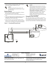
Emergency Power Off (EPO)
The external emergency stop facility is identical to
that described for the single unit installation — that
an individual emergency stop button is provided for
each unit. Note that this is a Normally Open switch.
Figure 3 Connecting EPO push button
NOTE
The settings should be the same for all
modules within the parallel system, except
the UPS ID No.
NOTE
If one module cannot transfer to inverter
mode long after its inverter is on, its output
connection may not be good or its output
phase rotation may not be coincident with
other modules. At this time, the LCD for the
UPS module will display “inverter
asynchronous” and the inverter indicator
will flash continuously. If either UPS
module makes abnormal noise after it
transfers to inverter, its parallel cables may
be incorrectly connected.
EPO-H
EPO
Monitor board
EPO-L
X2
UPS1
UPS2
EPO-H
Monitor board
EPO-L
X2