


INSTR,AM-RRR
Linear P/N: 212045 B
Material: 20 Lb. Mead Bond
Size: 8.500" x 11.000"
Ink: Black
Scale: 1-1
Side 2 of 2
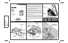
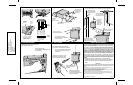
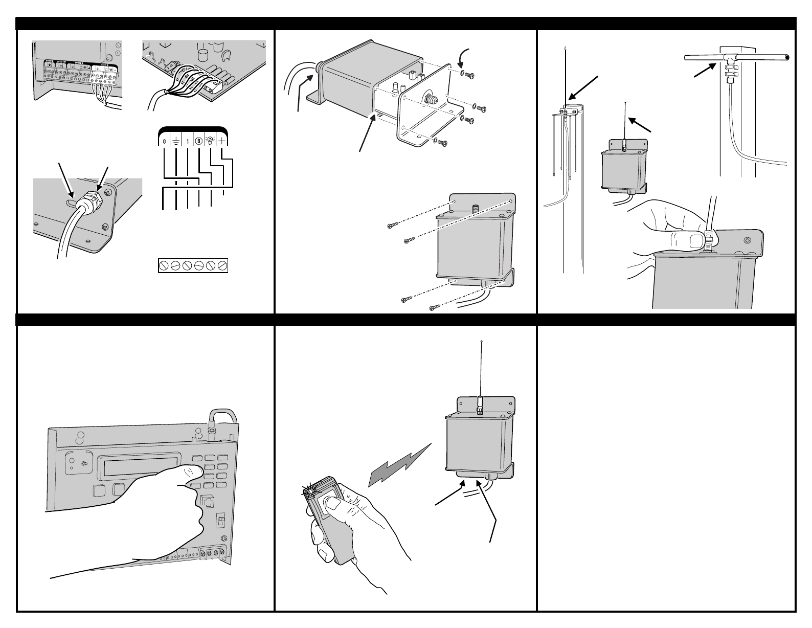
5. CONNECT AM-RRR TO AM/II 6. CLOSE CASE AND MOUNT UNIT 7. INSTALL ANTENNA
8. PROGRAM RECEIVER 9. TEST SYSTEM LINEAR LIMITED WARRANTY
This Linear product is warranted against defects in material and workmanship for twelve
(12) months. The Warranty Expiration Date is labeled on the product.
This warranty
extends only to wholesale customers
who buy direct from Linear or through Linear’s
normal distribution channels.
Linear does not warrant this product to consumers.
Consumers should inquire from their selling dealer as to the nature of the dealer’s
warranty, if any.
There are no obligations or liabilities on the part of Linear
Corporation for consequential damages arising out of or in connection with use
or performance of this product or other indirect damages with respect to loss of
property, revenue, or profit, or cost of removal, installation, or reinstallation.
All
implied warranties, including implied warranties for merchantability and implied
warranties for fitness, are valid only until Warranty Expiration Date as labeled on the
product.
This Linear Corporation Warranty is in lieu of all other warranties express
or implied.
All products returned for warranty service require a Return
Product Authorization Number (RPA#). Contact Linear Technical
Services at 1-800-421-1587 for an RPA# and other important
details.
IMPORTANT !!!
Linear radio controls provide a reliable communications link and fill an important need
in portable wireless signalling. However, there are some limitations which must be
observed.
✶
For U.S. installations only: The radios are required to comply with FCC Rules and Regulations as Part 15
devices. As such, they have limited transmitter power and therefore limited range.
✶
A receiver cannot respond to more than one transmitted signal at a time and may be blocked by radio signals
that occur on or near their operating frequencies, regardless of code settings.
✶
Changes or modifications to the device may void FCC compliance.
✶
Infrequently used radio links should be tested regularly to protect against undetected interference or fault.
✶
A general knowledge of radio and its vagaries should be gained prior to acting as a wholesale distributor or
dealer, and these facts should be communicated to the ultimate users.
Copyright © 2000 Linear Corporation 212045 B
SLIDE BOARD INTO
3RD SLOT UP
SECURE CASE
WITH FOUR
SCREWS AND
WASHERS
ATTACH CASE TO
MOUNTING SURFACE
USE SCREW ANCHORS
OR APPROPRIATE HARDWARE
FOR MOUNTING
TIGHTEN
AFTER
INSTALLATION
OMNI-DIRECTIONAL
EXA-1000 ANTENNA
MOUNTED ON POLE
LOCAL WHIP
ANTENNA
(SUPPLIED)
CONNECTED
DIRECTLY TO
RECEIVER
DIRECTIONAL
EXA-2000 ANTENNA
MOUNTED ON POST
CHOOSE AN ANTENNA TO FIT THE INSTALLATION REQUIREMENTS
FOLLOW EXA ANTENNA
INSTRUCTIONS WHEN
CONSTRUCTING ANTENNA
SCREW CONNECTOR
ONTO RECEIVER
INDICATOR
VIEWING
WINDOW
PWR (RED)
GND (BLK)
DAT1 (WHT)
DATO (GRN)
DVAL (BLU)
CLK (ORG/YEL)
(RED)
(BLK)
(GRN)
(WHT)
(BLU)
(ORG/YEL)
READER IN
USE CABLE FORMULA
TO DETERMINE CABLE
TYPE AND MAXIMUM
LENGTH
AM/II
B
O
1
O
O
O
1
1
1
B
AM-RRR
AM/II
TERMINALS
AM-RRR
TERMINALS
ROUTE WIRE THROUGH
STRAIN RELIEF BEFORE
WIRING TO TERMINALS
(TIGHTEN LATER)
WIRING
STRAIN
RELIEF
PROGRAM THE AM/II TO CONFIGURE
THE REMOTE RECEIVER
REFER TO THE AM/II
PROGRAMMING INSTRUCTIONS
FOR DETAILS
TEST TRANSMITTERS FROM VARIOUS
LOCATIONS TO DETERMINE RADIO RANGE
RECEPTION PATTERN WILL VARY
DEPENDING ON ANTENNA USED
AND SUROUNDING STRUCTURES
ADJUST THE INTERNAL RADIO RANGE
KNOB TO LIMIT RADIO RECEPTION
IF REQUIRED
RADIO INDICATOR WILL
FLICKER AS SIGNAL IS
RECEIVED
STATUS INDICATOR WILL
LIGHT RED WHEN POWER
IS APPLIED AND GREEN WHEN
ACCESS IS GRANTED