


+
D.C. FUSE
INPUT
1
+
+
MAIN IN
R
L
R
1
L
2
R
L
OUTPUT
LEVEL
VOICE
THR.
TAPE OUT
0 50V 70V 100V
POWER OUTPUTS
AUX IN
PRE OUT
0
25V
PHANTOM
24V
MIC
MIC/LINE
LINE
ON
OFF
H.P. L.P.
INPUT
3
INPUT 1
IN
INPUT
2
Vdc
LED
Vdc
300mA
INPUT
4
PRIORITYGND
FILTER
+
POWER INPUT
24V D.C.
COMMANDS
ON
OFF
PRIORITYGND
CHIME
LEVEL
VOLTAGE
SELECTOR
SEE INSTRUCTION MANUAL
ELECTRIC SHOCK HAZARD
REFER SERVICING TO QUALIFIED PERSONNEL
DO NOT REMOVE COVER
CAUTION:
THE FOLLOWING ARE TRADEMARKS/REGISTERED TRADEMARKS OF MACKIE DESIGN INC.: "MACKIE", "MACKIE INDUSTRIAL", & THE "RUNNING MAN" FIGURE
CONCEIVED, DESIGNED, AND MANUFACTURED BY MACKIE INDUSTRIAL • MADE IN ITALY • PATENTS PENDING • COPYRIGHT ©1999
-
-
-
-
LINE
50/60 Hz-115/230V
POWER OUTPUTS
4
POWER
AUX
INPUT LEVELS
AUX
1
2
INPUT
3
INPUT
1
INPUT
2
INPUT
4
LOW
EQ
HIGH
VOLUME
PEAK
OVERLOAD
SIGNAL
ON
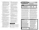
AM 4160 - P.A. AMPLIFIER
1
3
4
5
6
7
9
0
10
82
1
3
4
5
6
7
9
0
10
82
1
3
4
5
6
7
9
0
10
82
1
3
4
5
6
7
9
0
10
82
1
3
4
5
6
7
9
0
10
82
0
10
82
1
3
4
5
6
7
9
8
4
2
0
2
4
8
-10
+10
66
8
4
2
0
2
4
8
-10
+10
66
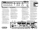
Front Panel Features
INPUT LEVELS knobs are used to adjust
the volume of the sound sources
connected to INPUTs 1-4 and AUX IN. To
prevent the levels from being modified,
the knobs can be removed and the holes
can be covered using the supplied inserts.
AUX selector is used to select the AUX IN
signal that is routed to the output. Only
one AUX IN can be selected at a time.
LOW EQ is a shelving filter that provides
12 dB of boost and cut below 100Hz.
HIGH EQ is a shelving filter that provides
12 dB of boost and cut above 10kHz.
VOLUME is a master volume control used
to adjust the overall volume of the signal
at the POWER OUTPUTS.
The POWER switch turns the AM4000
Series on and off.
The OVERLOAD indicator lights when the
amplifier is operating in overload, a
condition generally caused by a problem
on the speaker line. When the amplifier is
switched on, the OVERLOAD light comes
on for a few seconds. This is normal and
does not indicate a problem.
The SIGNAL indicator lights when a signal
is present at the POWER OUTPUTS.
The PEAK indicator lights when the output
signal is approaching clipping.
The ON indicator lights when the AM4000
is turned on and ready for operation.
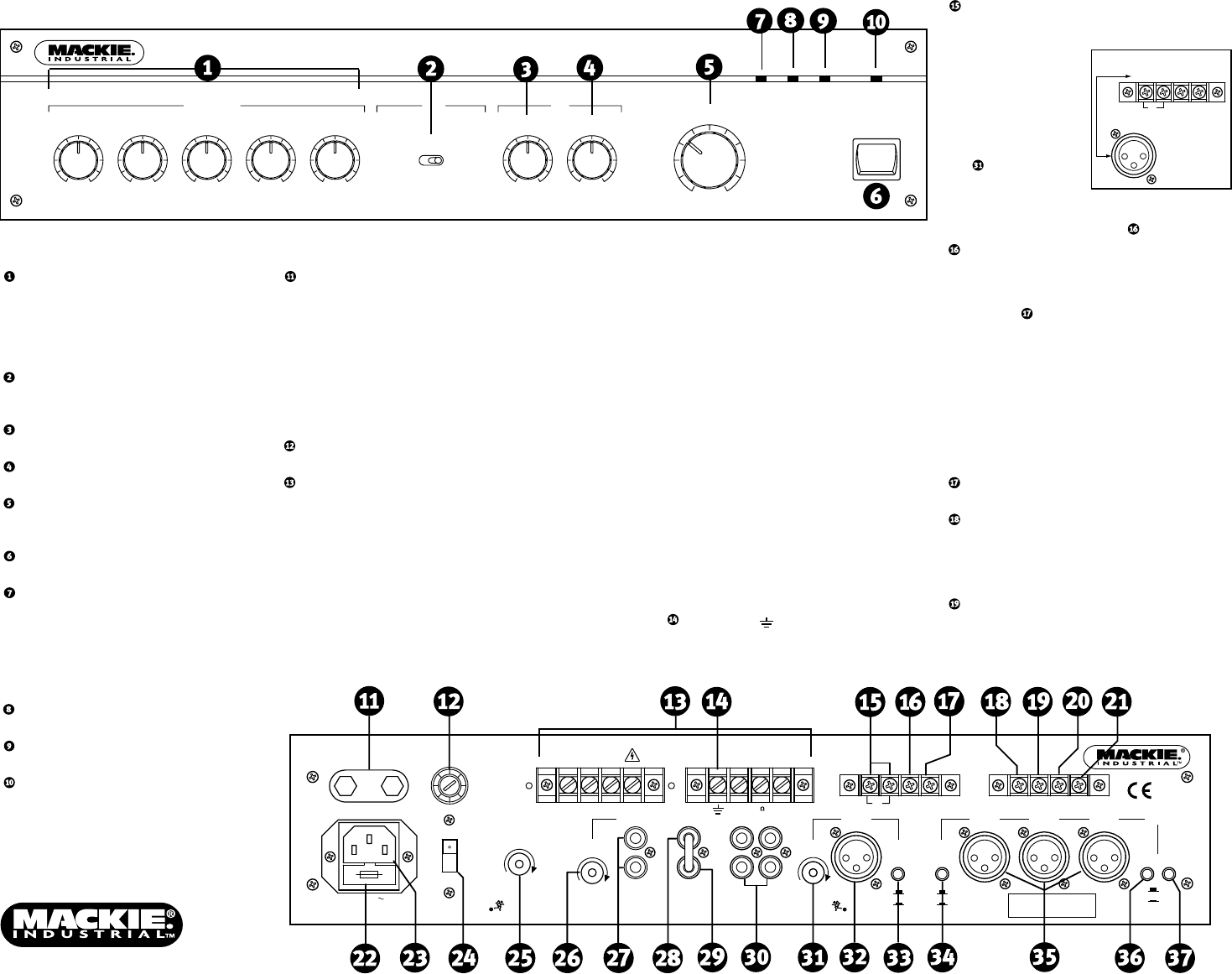
Rear Panel Features
POWER INPUT provides a means to
connect an external 24 VDC power supply
or battery as an alternative or backup
power source. The AM4000 Series
seamlessly switches to the backup supply
if there's an AC power loss. When both AC
power and 24 VDC power are connected,
the DC power is switched off.
Note: The unit is not equipped with
battery charging capabilities.
The D.C. FUSE protects the DC POWER INPUT
circuit. Replace with the same type fuse only.
POWER OUTPUTS are screw-terminal
connections for connecting speakers to the
4-ohm, 25V, 50V, 70V, or 100V outputs.
WARNING: To prevent the risk of electric
shock, never touch the bare wires coming
from the output terminals of the amplifier
when it is switched on. When the
connections have been made, insulate
the output terminals of the amplifier
using the protective cover provided.
Constant-Impedance Output
The total impedance of the speakers and
cable connected to the "4Ω" constant-
impedance output should be 4 ohms.
Connect the "4Ω" terminal to the "+"
(HIGH) speaker terminal, and the "0"
terminal to the "–" (LOW) speaker terminal.
Constant-Voltage Output
In a constant-voltage system, each
speaker must be equipped with a line
transformer having an input voltage equal
to that of the speaker line (e.g., 25V, 50V,
70V, or 100V). Typically, these line
transformers have selectable power taps
(i.e., 2.5W, 5W, 10W) for connecting to the
constant-voltage line. CAUTION: The sum
of the wattage values of the speakers must
not exceed the output power of the
amplifier.
Connect the appropriate POWER OUTPUT
voltage terminal to the "+" (HIGH) leg and
the "0" terminal to the "–" (LOW) leg of the
distributed speaker system.
The ground ( ) terminal is internally
connected to the chassis and safety
ground on the AC linecord.
The INPUT 1 IN terminals are parallel
with the INPUT 1 XLR connector and
accept a balanced mic or line-level signal.
INPUT 1 has a priority
function for paging
purposes, and
attenuates all other
inputs when a signal
is present at its input.
Use the VOICE THR.
control to adjust
the threshold for the
voice-activated circuit. Activation of the
priority function can also be accomplished
using the INPUT 1 PRIORITY terminal.
The INPUT 1 PRIORITY terminal activates
the priority function for INPUT 1 by using
an external normally-open switch to short-
circuit the INPUT 1 PRIORITY terminal to
the GND (ground) terminal. When the
INPUT 1 PRIORITY function is enabled, all
other inputs are muted (no signal is
transmitted to the outputs). An internal
jumper changes the priority function so
that the other inputs are attenuated rather
than completely muted.
Enabling the INPUT 1 PRIORITY function
also enables the Vdc LED and Vdc 300mA
outputs on the COMMANDS terminal strip.
This GND terminal is the common connection
point for INPUT 1 IN and PRIORITY.
The Vdc LED terminal is active when INPUT
1 PRIORITY or COMMANDS PRIORITY is
enabled. This provides 18 VDC for driving
an LED to indicate when the INPUT 1
PRIORITY has been activated.
The Vdc 300mA terminal is also active when
INPUT 1 PRIORITY or COMMANDS PRIORITY
is enabled. This provides 18 VDC with a
maximum output capacity of 300mA for
driving an auxiliary relay.
INPUT
1
INPUT
1
IN
1
Pin 1
Pin 2
Pin 3
2
3
PRIORITY
XLR to Terminal Strip
Cross-Reference
GND