


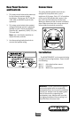


Rear Panel Features
and Controls
1. This rotary control selects the power tap
for the internal constant voltage
transformer. Choices are 1W, 2.5W, 5W,
10W, 20W, and BYPASS (used for 4Ω
operation).
2. This rotary control selects the constant
voltage distributed system in which the
speaker is used. Choices are BYPASS
(used for 4Ω operation), 0(Off), 25V, 50V,
70V, and 100V.
Note: Use a slot-head screwdriver to
adjust the rotary controls.
3. Use these spring-loaded terminals to
connect the speaker wiring.
Installation
The MONITOR MR3ST can be mounted using
the optional mounting brackets. These include
the following:
MA3-5 Articulated surface mount
MA3-6 U-bracket
MA-7B Wall-mount support bracket
WARNING: Consult a professional rigger or
structural engineer prior to suspending
loudspeakers from a structure not intended
for that use. Always know the working load
limit of the structure supporting the
loudspeaker array. Always make sure that
the rigging hardware minimum rating is at
least five times the actual load.
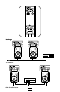
Connections
The spring-loaded speaker terminals are
designed to accept bare wire, up to a
maximum of 18 gauge. Strip 1/4” of insulation
off the end of the speaker wire, press in the
tab, and insert the bare wire into the hole.
When you release the tab, the wire is locked in
place. Make sure there are no stray strands of
wire outside the terminal connection.
+–
INPUT
4