


• SDI (SMPTE259M) (ITR-U601) with reclocked and shaped output
• Component Analog High Definition (SMPTE274M)
• Component Analog Standard Definition (SMPTE/EBU N-10))
• Composite PAL/NTSC (ITU-R BT.470/SMPTE170M)
• Y/C (S-Video)
• Active loop through is available for all analog signals
• Remote control options (Available Summer 2005)
• Small Footprint – occupies only 3RU of a standard EIA 19 inch rack
• Ready to mount – all brackets are factory installed
• Lightweight – 75% lighter than CRT models
• All adjustments and selections are readily available. No menus!
• Settings memory restores active state with power off/on cycle
• Easy to use front panel selection of inputs
• NTSC or Pal operation with automatic signal format detection
• All inputs automatically terminate
• Built in color bar generator for each display
• Includes V-PS12-5V-1 Universal power supply (U.L. class 2)
• Three LEDs (Red, Green, Amber) produce 7 different tally indications
• Unique 180 degree tilt adjustment
• Dry erase label for each screen
1
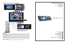
Product Overview
The Rack mounted and tiltable V-R72P-2SD represents leading edge technology in LCD imaging for broadcast and profes-
sional video applications featuring High Resolution, megapixel, TFT screens with completely digital signal processing. All
SMPTE/ITU video standards and signal types are accepted and displayed on each screen of this model. Analog signals are
digitized using an advanced 10 bit process on each signal path with 4x over sampling and adaptive 5 line comb fi lter with ex-
acting color space conversion. All video formats are scaled to fi t on screen in the highest resolution using a state of the art LSI
that incorporates 4x4 pixel interpolations with precision Gamma correction to produce the best images available.
2
Features
Analog and Digital Screen Formats and Frame Rates
All signal types and frame rates are automatically detected
• 525 – 60i / 625 - 50i (Interlaced NTSC/PAL)
• 720 x 486P (Progressive)
• 720 x 576P (Progressive)
• 720 x 1280 – Analog-50P, 59.94P, 60P /Digital 23.97P, 24P, 25P, 50P, 59.94P, 60P (Progressive)
• 1035 x 1920 - 59.94i, 60i (Interlaced)
• 1080 x 1920 – 50i, 59.94i, 60i / 23.973Psf, 24Psf, 25Psf, 29.97Psf, 30Psf
Psf=Progressive or Segmented Frame formats
V-PS12-5V-1
Universal power supply
(U.L. class 2)
3 RU
5.14”
13.5 cm
3
Electrical Specifications
Number of Screens 2
Screen Aspect 16:9/4:3 switchable
Display (Viewing Area) 7” (6.14”H × 3.27”V) (156.0mm x 83.28mm)
Viewing Angles 1300H x 1200V
Resolution (Dots) 800H × RGBx480V (1.2 million pixels)
Dot Pitch 0.065mm (W) x 0.175mm (H)
Pixel Response <30ms
Brightness (in cd/m²) 380 cd/m²
System NTSC/PAL auto recognition for standard definition signals
Inputs per display
Composite with active loop (BNC)
Y/C (SVideo) with active loop (4 Pin Mini Din Female)
SDI with re-clocked output (BNC)
Analog Component Y-Pr-Pb with active loop (3 BNC)
Outputs per display Active Composite loop through BNC
Reclocked SDI loop through BNC
10 bit Analog composite conversion of SDI signal BNC
Color Bar Signal Full field SMPTE
Power required 12 V D.C. from external U.L. Class 2 power supply (included) max 5.0 AMP
Power Consumption 24 Watt Nominal
Operating temperature
32 ̊ F to 110 ̊ F (0 ̊ C to 45 ̊ C)
2
3
V-R72P-2SD
V-R72P-2SD
Users Guide
Users Guide
Marshall Electronics
Dimensions 19.125”W x 2.5”D x 5.14”H (48.5cm x 6.35cm x 13.5cm)
V-R72P-2HD Weight 5.0 lbs (2.27kg)
V-PS12-5V-1 Power Supply Weight 1 lbs (0.45kg)
4
Mechanical Specifications
5
Operational Setup
1. Unpack the V-R72P-2SD and accompanying V-PS12-5V-1 power supply. Physically inspect for any damage that may have
occurred during shipping. Should there be any damage, immediately contact Marshall Electronics at 800-800-6608. If you
are not located within the continental united states call +1 310-333-0606.
2. After inspection, install in your desired location of a standard EIA 19-inch equipment rack. Adequate ventilation is required
when installed to prevent possible damage to the V-R72P-2SD internal components.
3. Connect required cables for signal input and output. Please note that power must be applied to the V-R72P-2SD for all
outputs to be activated. All BNC connectors should be rated for 75Ω.
4. Plug the V-PS12-5V-1 power supply into the A.C. source
5. Attach twist lock power connection from V-PS12-5V-1 power supply to the back of the unit.
6. Turn on the V-R72P-2SD by depressing the power switch located on the front of the unit.
6
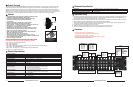
Connectors
* Composite Video Inputs comply to SMPTE-170M
* Component Inputs comply to SMPTE274M, 294M,295M,296M
* SDI inputs comply to SMPTE259M / ITU-R BT601
* Composite Video and SDI Outputs Require Power to be applied for activation
* Tally lamps active when connected to ground
S-Video In
4 Pin Din (Female)
Pin1 - GND
Pin2 - GND
Pin3 - Yin
Pin4 - Cin
Monitor 2
SDI In
Monitor 2
Component Video
In
Pb/Pr/Y or
Cb/Cr/Y
Mon 2
S-Video
In
Monitor 2
Composite
Video In
Monitor 1
Component Video
In
Pb/Pr/Y or
Cb/Cr/Y
Monitor 1
Composite
Video In
Pin1-M2Yel
Pin2-M2Red
Pin3-M2Grn
Pin4-
Pin5-Gnd
Pin6-
Pin7-
Pin8-
Pin9-
Pin10-
Pin11-M1Yel
Pin12-M2Red
Pin13-M3Grn
Pin14-
Pin15-Gnd
Tally IN
DB-15 Female
Active Outputs require power to be applied
All input signals appear as output signal
HDSDI/SDI signals are reshaped and re-clocked
Analog output signals are buffered and amplifi ed
Active Outputs require power to be applied
All input signals appear as output signal
HDSDI/SDI signals are reshaped and re-clocked
Analog output signals are buffered and amplifi ed
12 VDC from
V-PS12-3.3A
power supply
Left Pin - Pos
Right Pin- Neg
S-Video Out
4 Pin Din (Female)
Pin1 - GND
Pin2 - GND
Pin3 - Yout
Pin4 - Cout
Monitor 1
SDI In
Mon 1
S-Video
In