


QS216
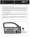
We strongly recommend that you have your new Q
series speakers installed by your authorized MB
Quart dealer. The installation professionals
employed by your dealer have the necessary tools
and experience to disassemble your vehicle, install
your new speakers and reassemble everything
properly. If you prefer to perform your own
installation, it is very important that you read the
entire manual first.
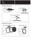
GETTING STARTED:
- Turn off the audio system.
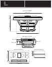
- Check clearance on both sides of mounting
surface to ensure that there are no obstructions
(windows, tracks, wiring etc).
CROSSOVER NETWORK INSTALLATION:
- Locate a dry location for mounting of your Q
Crossover Networks. DO NOT MOUNT IN
DOORS!
- Remove the cover of the crossover by squeezing
either side. This exposes the mounting holes for
securing the crossover to a flat surface. Prior to
pre-drilling pilot holes, ensure that you will not be
drilling into wiring, gas tanks, fuel lines etc.
- Once the crossover is mounted, snap the
protective cover back in place.
STANDARD
Crossover #1:
1. Connect Amplifier Channel 1 + to Crossover
WF + IN.
2. Connect Amplifier Channel 1 - to Crossover
WF - IN.
3. Connect Crossover WF + and - output to the
corresponding + and - on midrange speaker #1.
4. Connect the Red tweeter wire to the output
TW + on the Crossover.
5. Connect the Black tweeter wire to the output
TW - on the Crossover.
Crossover #2:
1. Connect Amplifier Channel 2 + to Crossover
WF + IN.
2. Connect Amplifier Channel 2 - to Crossover
WF - IN.
3. Connect Crossover WF + and - output to the
corresponding + and - on midrange speaker #2.
4. Connect the Red tweeter wire to the output
TW + on the Crossover.
5. Connect the Black tweeter wire to the output
TW - on the Crossover.
Bi-Amp
Crossover #1:
1. Connect Amplifier Channel 1 + to Crossover
WF + IN.
2. Connect Amplifier Channel 1 - to Crossover
WF - IN.
3. Connect Crossover WF + and - output to the
corresponding + and - on midrange speaker #1.
4. Connect Amplifier Channel 3 + to Crossover
TW + IN.
5. Connect Amplifier Channel 3 - to Crossover
TW - IN.
4. Connect the Red tweeter wire to the output
TW + on the Crossover.
5. Connect the Black tweeter wire to the output
TW - on the Crossover.
Crossover #2:
1. Connect Amplifier Channel 2 + to Crossover
WF + IN.
2. Connect Amplifier Channel 2 - to Crossover
WF - IN.
3. Connect Crossover WF + and - output to the
corresponding + and - on midrange speaker #2.
4. Connect Amplifier Channel 4 + to Crossover
TW + IN.
5. Connect Amplifier Channel 4 - to Crossover
TW - IN.
4. Connect the Red tweeter wire to the output
TW + on the Crossover.
5. Connect the Black tweeter wire to the output
TW - on the Crossover.
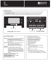
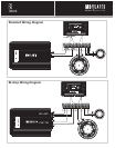
WIRING DIAGRAMS FOR STANDARD WIRING
AND BI-AMP WIRING
Standard Wiring Configuration: This wiring
configuration is used when you want to power
each crossover with a single amplifier channel. It
is important that you leave the jumper pins in
the locations shown in the diagram labeled
Standard.
Bi-Amp Wiring Configuration: This wiring
configuration is used when you want to power
each crossover with a pair of amplifiers(Bi-Amp) or
pair of channels (Bi-Wire). In this mode, the inputs
to the woofer’s low-pass filter and the tweeter’s
high-pass filter are electrically isolated. This
configuration is shown in the diagram labeled
Bi-Amp.