CHAPTER 2: THE MM-10XP SUBWOOFER
10
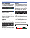
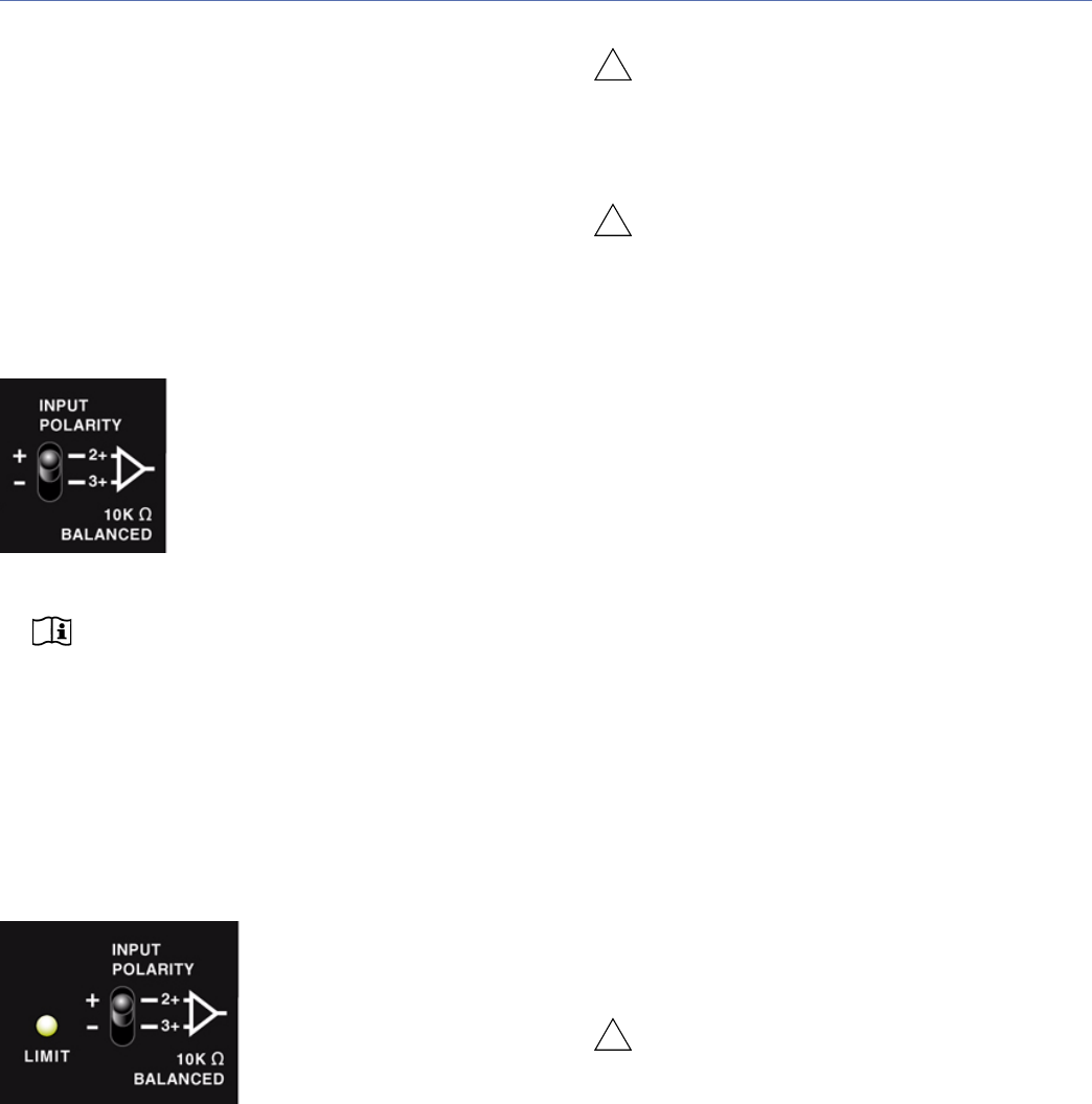
THE MM-10XP INPUT POLARITY SWITCH
The Input Polarity switch swaps the polarity of the audio
source signal, which is sometimes necessary to acoustically
align the subwoofer with other loudspeakers in the system.
When the switch is in the up (non-inverting) position, the
positive audio pin (+) is hot relative to the negative audio
pin (–), resulting in a positive pressure wave when a positive
signal is applied to the positive pin. When the switch is in the
down (inverting) position, the negative audio pin (–) is hot
relative to the positive audio pin (+), resulting in a positive
pressure wave when a positive signal is applied to the nega-
tive pin.
NOTE: The text for the Input Polarity switch on
the MM-10XP rear panel shows Pin 2 and
Pin 3, which is the convention used for the MM-10AC
and MM-10ACX models. However, the MM-10XP
Input Polarity switch actually reverses the polarity for
Pin 4 and Pin 5 of its input connector.
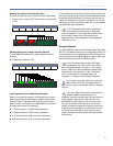
THE MM-10XP LIMIT LED
The MM-10XP has a three-color Limit LED on its rear panel
that changes color to indicate the subwoofer’s status.
Powering On (Green)
When powering up the MM-10XP subwoofer, the following
startup events occur and are indicated by the Limit LED:
1. The LED flashes green and then yellow during power up.
2. The LED turns solid green indicating the subwoofer is
ready to reproduce audio.
CAUTION: If the Limit LED turns red and stays
solid red after powering up and the audio is
muted, the subwoofer has encountered a failure and
may need to be serviced. Contact Meyer Sound
Technical Support.
CAUTION: If the Limit LED turns solid red and
the MM-10XP continues to output audio,
though at reduced levels, the subwoofer’s voltage
may have dropped below 25 V DC. When these con-
ditions are encountered, operation of the subwoofer
should cease and its power supply and cabling
should be verified.
Limiting (Yellow)
Limiting activity is indicated when the Limit LED turns yel-
low. When engaged, the limiter protects the subwoofer’s
driver and prevents signal peaks from causing excessive
distortion in the subwoofer’s amplifier, thereby preserving
headroom and maintaining smooth frequency responses at
high levels. When the level returns to normal, below the lim-
iter’s threshold, the LED turns green and limiting ceases.
The MM-10XP performs within its acoustical specifications
at normal temperatures when the Limit LED is green, or if the
LED turns yellow for two seconds or less and then returns to
green for at least one second. If the LED remains yellow for
longer than three seconds, the subwoofer enters hard limit-
ing where:
■ Increases to the input level have no effect.
■ Distortion increases due to clipping and nonlinear driver
operation.
■ The drivers are subjected to excessive heat and excur-
sion, which will compromise their life span and may
eventually lead to damage over time.
CAUTION: The Limit LED turns yellow when
the subwoofer’s signal rises 2 dB above the
limiting threshold, and indicates a safe, optimum level
has been exceeded. If the MM-10XP subwoofers in a
system begin to limit before reaching the desired
SPL, consider adding more subwoofers to the sys-
tem to achieve the desired SPL without exposing the
subwoofers to excessive levels and possible over-
heating.
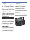
MM-10XP Input Polarity Switch
MM-10XP Limit LED
!
!
!


