


Operating Instructions
Meyer Sound Laboratories, Inc.
2832 San Pablo Avenue
Berkeley, CA 94702
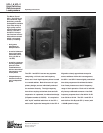
UPL-1 & UPL-2
High Definition
Reinforcement
Loudspeakers
Amplifiers and
Driver Protection
Independent power biamplifiers maximize system
headroom, efficiency and damping while minimiz-
ing distortion. The low frequency amplifier delivers
200 watts burst output power, while the high fre-
quency amplifier provides 100 watts. Both employ
complementary power MOSFET output stages
operating class A at moderate listening levels
(<90 dB SPL), and class AB at high levels.
The driver protection circuits employ thermo-pre-
dictive limiters and soft peak clamps to guard
against damage from excessive amplifier power
and ensure graceful overload characteristics.
Power and Fuses
The UPL-1 and UPL-2 accept AC voltages from 90
to 260 VAC, at 50 or 60 Hz, in four ranges. Select
the range that is closest to the local mains voltage.
Do not switch among AC voltage ranges with the
power cable connected to an outlet. The UPL-1
and UPL-2 require a grounded outlet. Never cut
the earth ground pin or “float” the mains ground.
Always set the voltage selector switch before con-
necting and operating the unit.
The unit is protected by a fast-acting fuse in the
voltage selector switch. If the fuse blows, check
the line voltage and voltage switch setting. Always
replace the fuse with the same type and rating.
Connections
The UPL-1 and UPL-2 present a 10k ohm input
impedance at a three-pin XLR-type receptacle
wired as follows:
Pin 1 — Audio common
Pin 2 — Signal low (-)
Pin 3 — Signal high (+)
Case — Earth (AC) ground
Shorting any input connector pin to the case may
form a ground loop and cause hum. Standard
audio cables with XLR-type connectors may be
used for balanced signal sources. Unbalanced
sources will require an in-line adapter.
Where multiple UPL-1’s or UPL-2’s are driven from
a single source, it is best to “mult” at the source
output and run individual shielded cables to each
of the loudspeaker inputs.
Be certain that the source equipment is capable of
driving the total load impedance presented by the
paralleled loudspeaker input circuits. For example,
since the input impedance is 10k ohms, a source
output that can drive 600 ohms will handle a maxi-
mum of 16 UPL-1’s or UPL-2’s in parallel
(625 ohms total load impedance). If any of the
paralleled loudspeakers loses power, however, it
may cause distortion in some, or all, of the others.
The best solution for driving multiple units from one
source is to use individual, isolated outputs. This
can be accomplished, for example, by assigning
one channel of a CP-10 Complementary Phase
Parametric Equalizer to each loudspeaker and
branching the source output to the CP-10 inputs.
The system may then be aligned using SIM
®
Sys-
tem II.
For professional balanced equipment, use the
+4 dBu setting. For semiprofessional and con-
sumer unbalanced equipment, use the -10 dBV
setting. Driving the UPL-1 or UPL-2 from a +4 dBu
source with the switch set to -10 dBV will result in
increased noise.
Note that the -10 dBV setting is
more sensitive
(designed for
lower
signal levels) than the +4 dBu
setting:
• +4 dBu position:
1.23 VRMS = 114 dB SPL
• -10 dBV position:
0.316 VRMS = 114 dB SPL
In normal operation, the rear-panel LED will glow
green. At high listening levels, the LED may flash
red on program peaks. This indicates the onset of
overload, where the loudspeaker protection limiters
are activated.
If the LED is continuously red for an extended
period (8 hours or longer), thermal damage may
result.
Sensitivity Switch
Signal / Overload
Indicator