


Chain Replacement with No Chain in Hoist
Refer to Figures 4 and 5.
1. DISCONNECT HOIST FROM POWER SUPPLY and move
hoist to a work table. Do not remove the electrical cover.
2. Lay the hoist on its side and remove the four screws that
attach the sheave housing to the gear housing (See Figure
12, Ref. No.2).
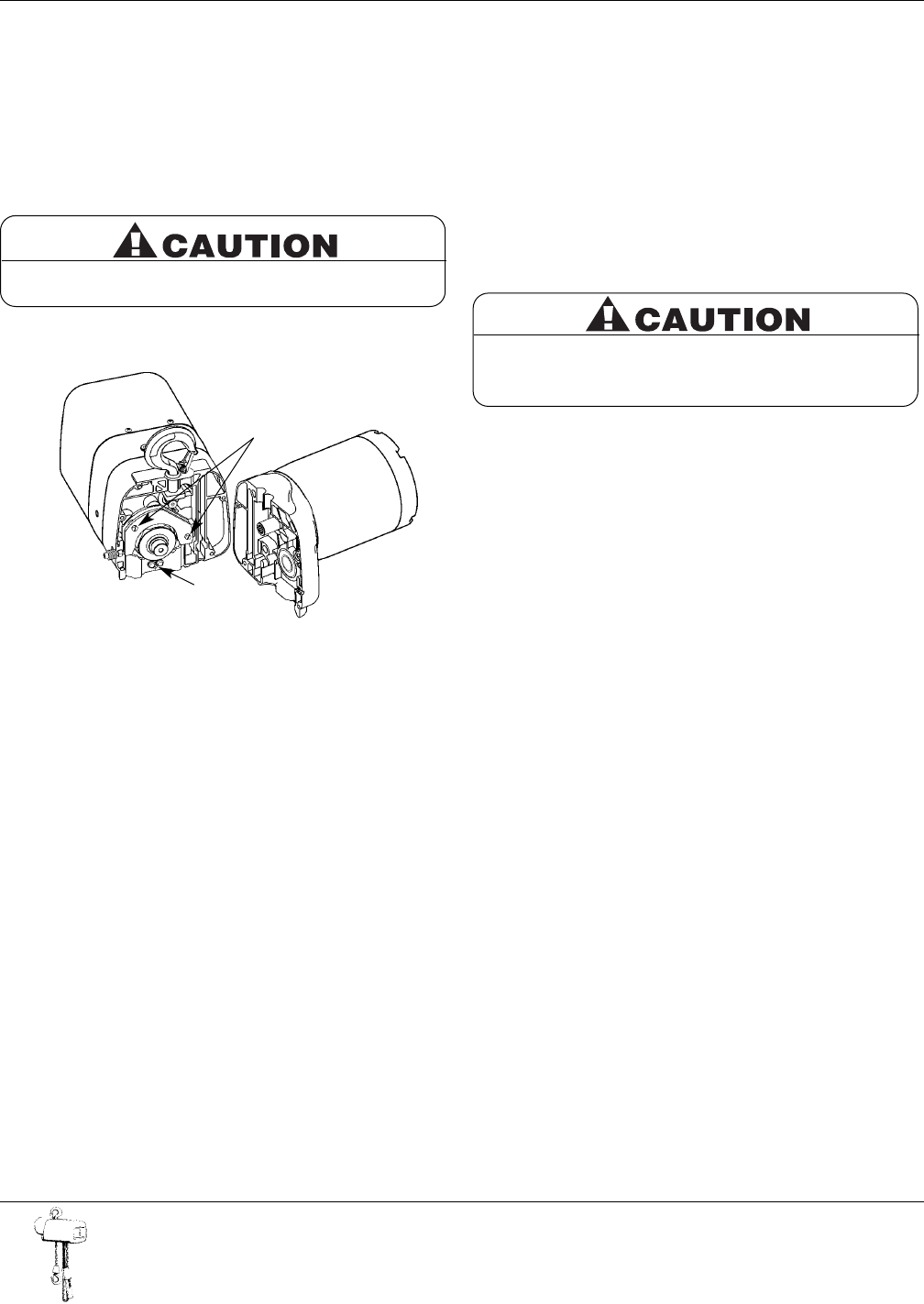
3. Carefully pull the sheave housing and motor assembly loose
from the gear housing.
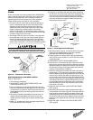
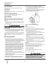
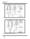
4. Turn the two hoist sections at right angles and remove the
chain guide screws on the nearest chain guide (Ref.No.1,
Figure 5).
5. Remove the two chain guide plate screws (Ref. No.2) and
the nearest chain guide plate. Be careful not to lose the two
spacers that are between the chain guide plates.
NOTE: Inspect chain guides and load sheave for wear, replace
as needed.
6. Lay the new chain over the load sheave.Allow about 15" of
chain below the hoist on the slack end (See Figure 4). Be sure
the welds of the upstanding links are out away from the load
sheave and that proper orientation is observed for attachment
of the dead end. Also be sure the load hook assembly (if
already attached to the chain) is toward the center of the hoist
or to your right as you face the load sheave.
7. Replace the chain guide plate and the chain guide. Grease
the splined shafts that project from both the housing and
the motor.
8. Place the motor coupling on the splined shaft and carefully
fit the two hoist sections together.Be sure the dead-end nut,
the top hook and the support screw (double-chained hoists
only) are all in place. On single-chained hoists, the hook
shank goes in the center hole; on double-chained hoists, it
goes in the off-center hole (See Figure 4). Be careful not to
pinch any of the wiring.Turn the hoist on its side and replace
the four screws and tighten securely.
9. Follow steps 11 through 14 in the previous section, CHAIN
REPLACEMENT WITH CHAIN IN HOIST, to complete the
chain replacement procedure.
LIMIT SWITCH ADJUSTMENT
IMPORTANT: Before placing hoist in operation, check the limit
switch adjustment. Limit switches are provided to protect the
hoist against damage resulting from overtravel or to allow
setting the hook travel within the factory-set limits of travel.For
easy identification and association with the proper direction of
travel, the upper and lower limit switch adjusting nuts are color-
coded gold and silver respectively.Each limit nut has 10 slots
for fine adjustment, and the increment of adjustment is such
that one slot is equivalent to approximately one link of chain
travel.Movement of the limit switch nuts toward or away from
each other increases or decreases the hook travel respectively.
Care should be exercised when adjusting either limit of travel.
Adjusting Upper Limit (Gold Nut)
Refer to Figure 3.
1. Suspend the hoist.For single-chained models raise the load
block until there is a minimum clearance of 2" from the hoist
housing and the top of the block. Double-chained models
require a minimum clearance of 1" from the chain support to
the top of the load block.
2. DISCONNECT HOIST FROM POWER SUPPLY and
remove the electrical cover.
3. With a screwdriver, pry the spring guide plate out of the slots
in the limit switch nuts.
4. Turn the slotted gold nut toward its limit switch until the
switch “clicks” then turn two slots farther. Release the spring
guide plate and be sure it slips back into the slots in both
limit switch nuts.Do not disturb the silver slotted nut if it has
been set previously.
Adjusting Lower Limit (Silver Nut)
Refer to Figure 3.
1. Suspend the hoist.Carefully lower the load block to a point
where the slack-end loop of the chain hangs down 6" or
more from the hoist housing (or the limit desired in any
particular application allowing the minimum 6").There
should be a minimum clearance of 1½" between the chain
stop and the bottom of the hoist.
2. DISCONNECT HOIST FROM POWER SUPPLY and
remove the electrical cover.
3. With a screwdriver, pry the spring guide plate out of the slots
in the limit switch nuts.
4. Turn the slotted silver nut toward its limit switch until the
switch “clicks,” then turn two slots farther.Release the spring
guide plate and be sure it slips back in the slots in both limit
switch nuts.Do not disturb the gold slotted nut if it has been
set previously.
Check Both Upper and Lower Limits
1. Connect the hoist to the power supply.Be sure the green
ground wire is properly grounded .
2. Check load hook direction (See INSTALLATION 2-c, page 5).
8
Milwaukee Electric Tool Corporation
13135 West Lisbon Road
Brookfield, Wisconsin 53005
TEL: (800) 729-3878
If the wires running to the limit switches are ever
disconnected for any purpose, be sure to replace
wires in accordance with the correct wiring diagram
(See WIRING DIAGRAMS, page 12).
Figure 5 — Chain Replacement with No Chain in Hoist
1
2
There are wires running through the hoist. Carefully
ease the hoist sections apart. Do not jerk them apart.